
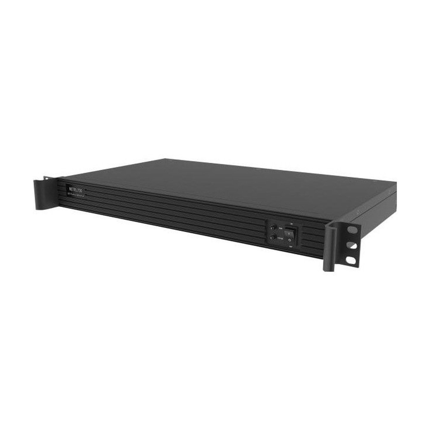
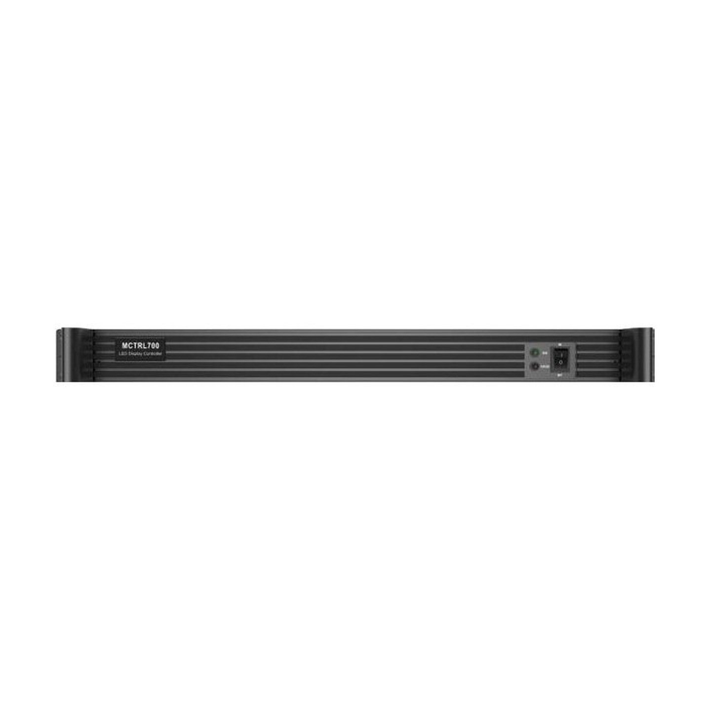
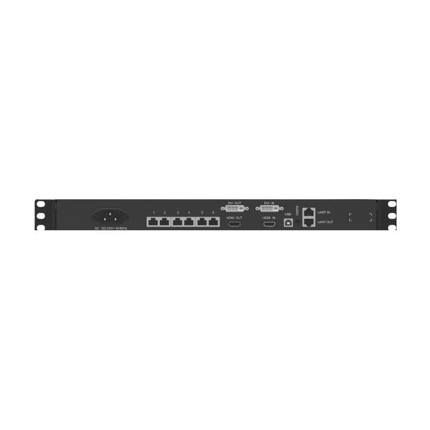
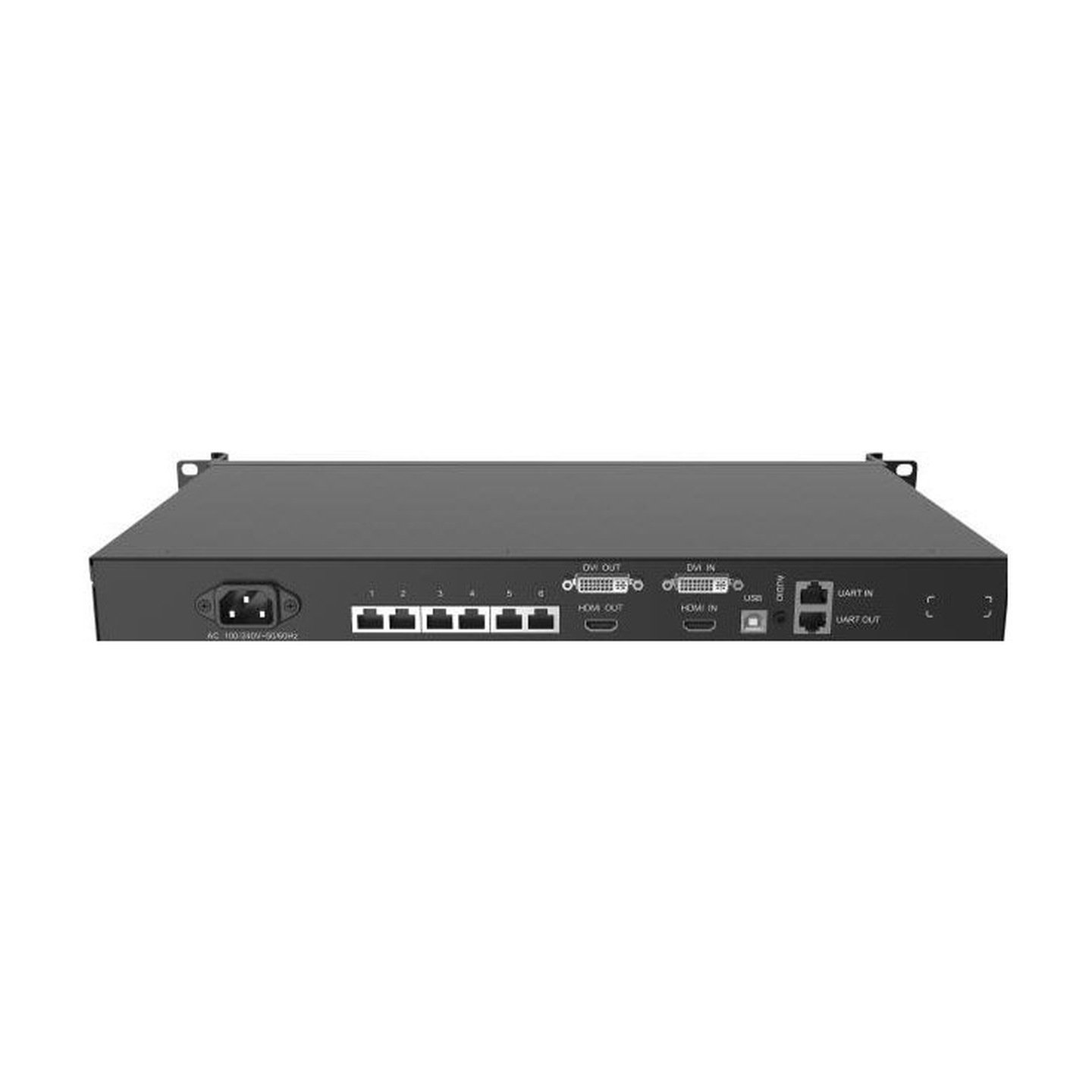
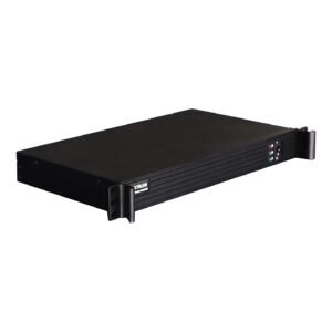
The NovaStar MCTRL700 is a 1U LED sending controller for systems that already have a finished HDMI or DVI canvas. It accepts one HDMI 1.3 or single-link DVI source, maps the image across six Gigabit Ethernet outputs, and supports video loop-through, multi-controller cascading, and Ethernet-port redundancy.
The controller's job is sending and mapping, not video processing. It does not scale a source, build layers, or switch between sources like a presentation processor. If your computer or media server cannot provide the final screen resolution, place a suitable video processor before the MCTRL700.
Why the MCTRL700 has six Ethernet ports but a 2.30-million-pixel ceiling
The current NovaStar specification sets the MCTRL700's total loading capacity at 1920×1200@60Hz, which is 2,304,000 pixels. Each Ethernet port can carry up to 650,000 pixels, but the six port limits cannot be added together to create a 3.9-million-pixel canvas. Both the complete canvas and every individual port must stay within their own limits.
Six outputs are still useful. They let you divide the same 2.30-million-pixel canvas into more cabinet chains, shorten long data runs, and reserve ports for backup. That can make the MCTRL700 a better fit than a four-port controller even when both models support the same total input resolution.
| Example canvas | Total pixels | Initial MCTRL700 check |
|---|---|---|
| 1920×1080 | 2,073,600 | Within the total limit; verify each Ethernet-port load |
| 1920×1200 | 2,304,000 | At the current documented ceiling |
| 3840×600 | 2,304,000 | Supported maximum-width example; the source must output this custom timing |
| 500×3840 | 1,920,000 | Within the total and current maximum-height example |
| 2560×960 | 2,457,600 | Over the total limit; use a higher-capacity or multi-controller design |
Pixel count is the first check, not the whole design. The receiving-card type, cabinet map, and number of pixels assigned to each output still need to be confirmed before installation.
MCTRL700 specifications
The table below uses NovaStar's current MCTRL700 V1.2.2 specification. It separates the controller-wide limit from the per-port limit so the capacity is not overstated.
| Specification | MCTRL700 |
|---|---|
| Video inputs | 1× single-link DVI IN; 1× HDMI 1.3 IN; 1× audio input |
| Video loop outputs | 1× single-link DVI OUT; 1× HDMI 1.3 OUT |
| Maximum total load | 1920×1200@60Hz, 2,304,000 pixels |
| Current documented source format | 8-bit RGB 4:4:4 |
| Custom resolution limits | Up to 3840 px wide at 3840×600@60Hz; up to 3840 px high at 500×3840@60Hz |
| Interlaced input | Not supported |
| HDCP | HDCP 1.4 on HDMI and DVI inputs |
| LED outputs | 6× Gigabit Ethernet, up to 650,000 pixels per port |
| Redundancy | Redundancy between Ethernet ports; hot-backup verification supported |
| Audio over data outputs | Ethernet ports 1–2 |
| Computer control | USB Type-B 2.0 |
| Device cascading | UART IN/OUT; up to 20 devices |
| Input power / rated consumption | AC 100–240V, 50/60Hz; 12 W |
| Dimensions / rack size | 482.0×268.5×44.4 mm; 1U |
| Net weight | 2.6 kg |
| Operating environment | –20°C to +60°C; 10%–90% RH, non-condensing |
| Included accessories | Power cord, USB cable, DVI cable |
For connector drawings, environmental notes, and the complete source table, use the MCTRL700 datasheet PDF.
MCTRL700 HDMI and DVI loop-through vs UART cascading
The rear panel supports two different kinds of chaining, and they solve different problems.
The HDMI OUT and DVI OUT connectors pass a video source onward. For example, one prepared HDMI canvas can enter the first MCTRL700, leave through HDMI OUT, and feed the next controller. This reduces the need for a separate distribution amplifier in a simple multi-controller rack, although the complete signal path still needs to be tested for the required cable length and source format.
UART IN and OUT carry device-control communication, not the LED image. Up to 20 MCTRL700 units can be linked so they can be managed as a controller chain. In a multi-unit system, plan both paths: loop the video signal through the matching DVI or HDMI connectors, then connect UART for control cascading.
MCTRL700 setup: prepare the source before mapping the LED wall
Start with the final LED canvas, not with the six Ethernet ports. Calculate the screen's total width and height, confirm that the result fits within 2,304,000 pixels, and decide how the cabinets will be divided across the available outputs. No port may exceed 650,000 pixels.
Next, set the computer, media server, or upstream processor to a supported progressive resolution. The MCTRL700 does not scale video, so a source sent at the wrong size will not be resized to fit the LED wall. A 3840-pixel-wide custom timing can work only when its height keeps the total within the controller limit; 3840×2160 is not supported.
Connect a Windows computer to the USB Type-B control port and open NovaLCT. Load or read the correct receiving-card configuration, map the cabinets in their actual cable order, send the configuration to the hardware, and save it after the complete wall has been checked. If the front RUN indicator shows no valid video, confirm the source timing and cable before changing the cabinet map.
Basic files can be prepared before the wall arrives, but final port mapping, redundancy, color, and calibration should be tested with the real cabinets and signal chain.
MCTRL700 Ethernet redundancy and backup-port planning
Ethernet redundancy gives the screen a second data path if a primary cable or output path fails. It does not increase the number of pixels the controller can display. A backup port protects cabinets already counted in the main canvas, so it must be included in the port plan from the start.
For a critical fixed installation, decide which cabinet chains require backup before using all six ports for live data. A breathing RUN light indicates that redundancy has taken effect, but the rack light is only a status check. Interrupt the primary path during commissioning and confirm that the intended cabinets remain active.
MCTRL700 applications
Touring racks with repeated video feeds
The 1U chassis, HDMI/DVI loop outputs, and UART cascade ports suit racks where the same prepared source must reach several controller sections.
Wide or irregular walls within 2.30 million pixels
Six Ethernet outputs provide more ways to divide cabinet chains across a shallow banner, tall display, or irregular cable layout, as long as the total and per-port limits are respected.
Fixed installations that need cable backup
Control rooms, houses of worship, retail features, and venue displays can reserve ports for redundancy instead of using every output only for live load.
Multi-controller LED systems
Up to 20 units can be cascaded for control, while HDMI or DVI loop-through carries the prepared video signal from one controller to the next. Larger systems still require a complete source-distribution and synchronization plan.
MCTRL700 manual, datasheet, firmware and NovaLCT downloads
NovaStar's reviewed resource set provides V1.2.2 specifications rather than a separate current MCTRL700 hardware manual. Use the datasheet for hardware limits and the linked official NovaLCT configuration guide for screen setup. For firmware, match the package to the exact MCTRL700 model and review its release notes before updating; do not use MCTRL700 Pro firmware on the original MCTRL700.
Firmware download: MCTRL700 firmware package. Match it to the exact hardware version, save the working configuration and read the release notes before updating.
Direct PDF links: MCTRL700 User Manual PDF · MCTRL700 Datasheet PDF
MCTRL700 vs MCTRL600, MCTRL660 and MCTRL660 Pro
These controllers can share the same 1920×1200@60Hz 8-bit class, but they solve different rack and source requirements.
| Best fit | Recommended model | Why |
|---|---|---|
| Four Ethernet outputs are enough and a light-sensor input is useful | MCTRL600 | Same current 8-bit total-resolution class with four outputs and ambient-brightness sensor support |
| Front-panel display, fast screen setup, and documented 10/12-bit input support matter more than six ports | MCTRL660 | Four outputs, LCD/knob control, quick screen configuration, and high-bit-depth modes at reduced resolution |
| Six output paths, loop-through, UART cascade, and port redundancy are the priority | MCTRL700 | More cabinet-chain and backup flexibility within the 2.30M total ceiling |
| 3G-SDI, Genlock, low-latency operation, or 10G optical transmission is required | MCTRL660 Pro | Built for live-production interfaces and optical workflows that the MCTRL700 does not provide |
If the source needs scaling, seamless switching, or multiple layers, none of those sending features replaces a processor. Add an upstream unit or choose an all-in-one model from the NovaStar video processors category.
Is the MCTRL700 right for your LED system?
Use the MCTRL700 when the source can output the final progressive canvas, the wall remains within 2,304,000 total pixels, and six Ethernet paths improve cabinet mapping or redundancy. Its HDMI and DVI loop outputs are also useful when the same prepared source must pass through several controller sections in a rack.
Consider the MCTRL660 when you need front-panel setup or verified higher-bit-depth input, and the MCTRL660 Pro when the project depends on SDI, Genlock, optical transmission, or low-latency operation. If the source must be resized, switched, or layered, keep the MCTRL700 in the sending role and place a suitable processor before it.
Before ordering, confirm the LED canvas, source timing, bit depth, receiving-card model, cabinet pixel size, port map, backup plan, and number of controller sections. Those details matter more than the number of RJ45 connectors alone.
MCTRL700 frequently asked questions
How many pixels can the MCTRL700 control?
NovaStar's current V1.2.2 specification lists a maximum total load of 1920×1200@60Hz, or 2,304,000 pixels. Each Ethernet output also has a separate limit of 650,000 pixels.
Do six 650,000-pixel ports make the MCTRL700 a 3.9-million-pixel controller?
No. The per-port ratings describe how much each output can carry, while the controller-wide ceiling remains 2,304,000 pixels. The port limits and total limit must both be satisfied.
Does the MCTRL700 scale video?
No. The source or an upstream video processor must create the final LED canvas. The MCTRL700 maps and sends that prepared image to the receiving cards.
Can the MCTRL700 accept a 4K source?
It does not accept a standard 3840×2160 4K UHD canvas. It supports certain custom timings with an axis up to 3840 pixels, such as 3840×600@60Hz, when the total load stays within 2,304,000 pixels.
Can HDMI and DVI be used as two switched or layered sources?
Do not treat the MCTRL700 as a two-source presentation switcher. It provides HDMI and DVI input choices with matching loop outputs, but source switching, scaling, and layers should be handled before the controller.
What is the difference between loop-through and UART cascading?
HDMI or DVI loop-through passes the video signal to another controller. UART links device control across a chain of up to 20 units. A multi-controller rack may use both connections.
Does the MCTRL700 support Ethernet backup?
Yes. It supports redundancy between Ethernet ports and hot-backup verification. Backup ports protect the same screen data and do not increase total capacity.
Which software is used to configure the MCTRL700?
Use NovaLCT on a connected Windows computer for receiving-card configuration, cabinet mapping, redundancy, saving to hardware, and supported calibration tasks.
Confirm the MCTRL700 six-port and backup plan before ordering
Show us how the 2.30-million-pixel canvas will be divided across the six outputs. Include the cabinet order on each port, which ports are reserved for backup, the HDMI or DVI loop-through chain, and the number of controller sections. With the source timing and receiving-card model, that information is enough to check whether the MCTRL700 layout works or needs a different controller or processor.
Reviews
There are no reviews yet.