
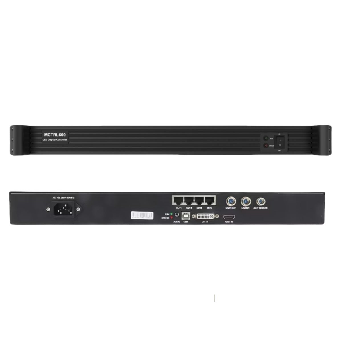
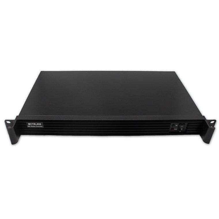
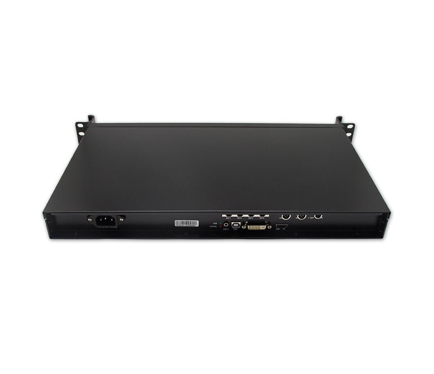
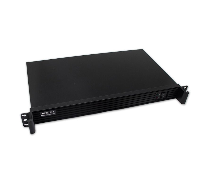
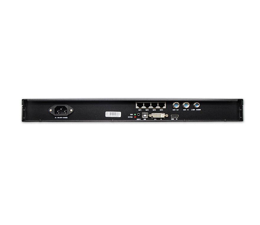
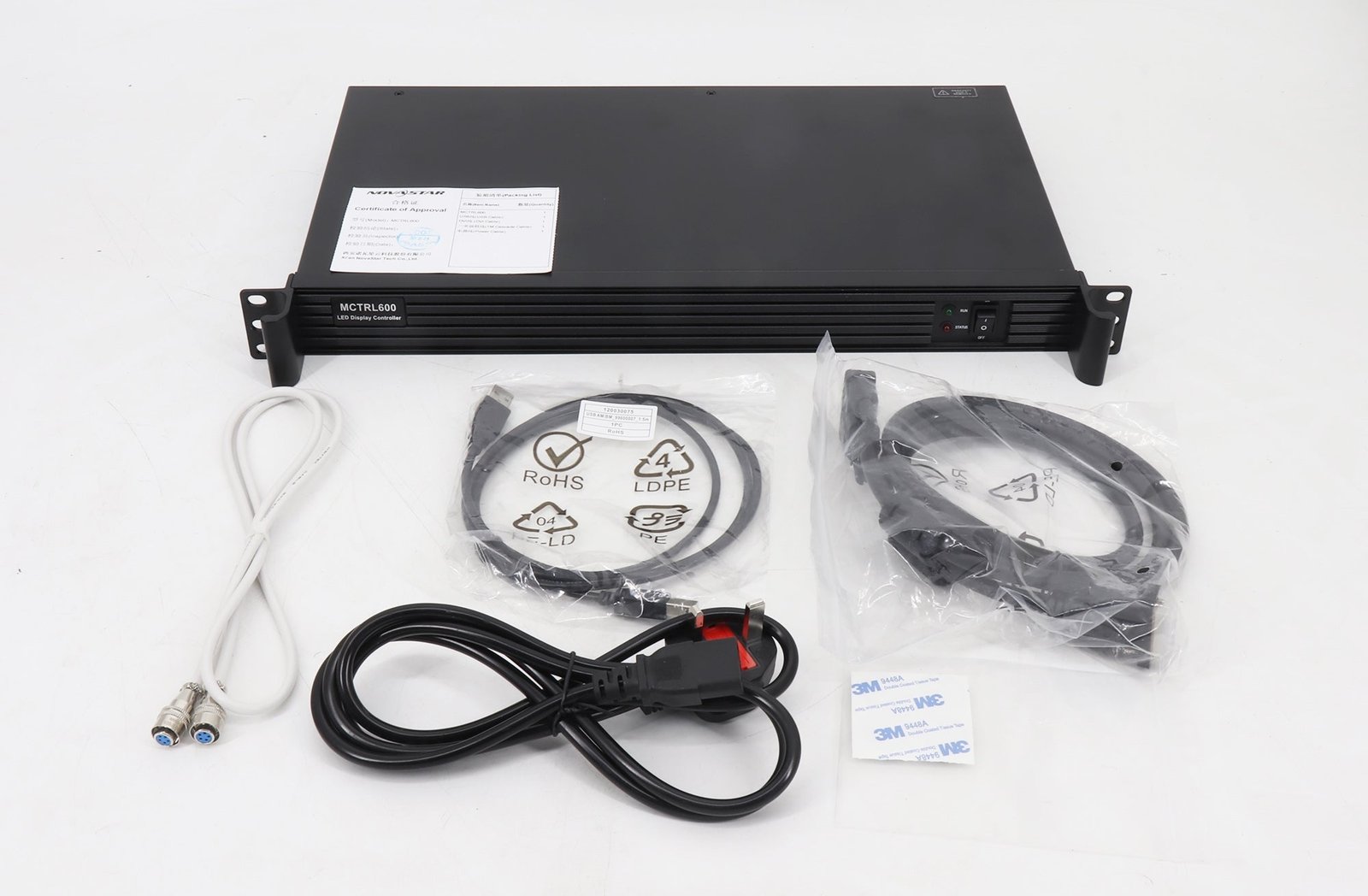
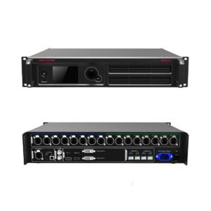
The NovaStar MCTRL600 accepts one prepared HDMI 1.3 or Single-Link DVI video source and maps it across four Gigabit Ethernet outputs for a NovaStar LED display. At 8-bit, the source can be as large as 1920 × 1200 at 60 Hz. The controller also supports custom input timings up to 3840 pixels wide or high when the total timing stays within its documented limits.
It is a sending controller, not an all-in-one video processor. The MCTRL600 does not create layers, scale mixed sources or provide seamless presentation switching. If the source does not already match the LED canvas, place a suitable video processor before the controller.
What the NovaStar MCTRL600 does in an LED system
One prepared HDMI or DVI canvas enters the MCTRL600 and is divided across four Ethernet outputs. The NovaStar receiving cards inside the cabinets use those four mapped data paths to drive the modules.
The source or an upstream processor must create the required screen timing first; the MCTRL600 does not resize a normal presentation into an unusual LED canvas. NovaLCT is then used to assign the cabinets and pixels to the four outputs.
Can the MCTRL600 drive your LED wall?
Check the full canvas first, then check the load assigned to each of the four Ethernet outputs. Passing one check does not guarantee the other.
| Example source canvas | Pixel count | Initial MCTRL600 check |
|---|---|---|
| 1920 × 1080 at 60 Hz | 2,073,600 | Within the standard 8-bit input ceiling; verify every port map |
| 1920 × 1200 at 60 Hz | 2,304,000 | At the documented 8-bit input ceiling |
| 3840 × 600 at 60 Hz | 2,304,000 | Documented ultra-wide example; source timing and port layout still need testing |
| 500 × 3840 at 60 Hz | 1,920,000 | Documented ultra-tall example; confirm the source can generate it |
| 2560 × 960 at 60 Hz | 2,457,600 | Above the current documented 1920 × 1200 / 2.304M input ceiling; do not approve it from an old reseller page |
Each Ethernet output can carry up to 650,000 pixels, but those four limits cannot simply be added to claim a 2.6-million-pixel canvas. The selected input format is the first ceiling. After the full source fits, divide the cabinets so that no individual output exceeds its own limit.
Bit depth changes the answer. At 10-bit or 12-bit, the current official maximum input is 1440 × 900 at 60 Hz, or 1,296,000 pixels. If a project needs both the full 1920 × 1200 canvas and high-bit-depth input, the MCTRL600 is not the right controller for that exact signal path; compare a newer controller or change the upstream format.
MCTRL600 HDMI, DVI and 8/10/12-bit input limits
HDMI 1.3 is the practical choice for a media player, computer or processor with an HDMI output. It supports HDCP 1.4, which can help with compliant protected sources, but the final source and content path still need to be tested. Single-Link DVI offers the same documented maximum resolutions for systems already built around DVI.
The connectors are alternative source inputs, not two independent layers. If a production needs several sources, picture-in-picture, scaling or seamless switching, use an upstream video processor and send one finished signal to the MCTRL600.
| Input format | Maximum documented input at 60 Hz | Practical consequence |
|---|---|---|
| HDMI 1.3 or SL-DVI, 8-bit | 1920 × 1200 | Full standard MCTRL600 input capacity |
| HDMI 1.3 or SL-DVI, 10-bit | 1440 × 900 | Lower source canvas; verify the media-server output format |
| HDMI 1.3 or SL-DVI, 12-bit | 1440 × 900 | Same lower maximum stated in V2.3.5 |
| Custom width | 3840 × 600 example | Useful for a long, shallow LED ribbon |
| Custom height | 500 × 3840 example | Useful for a narrow portrait display |
Both video inputs support RGB 4:4:4, YCrCb 4:4:4 and YCrCb 4:2:2 in the current source table. Interlaced signals are not supported, so confirm that the source is sending a progressive timing before troubleshooting the cabinet map.
MCTRL600 Ethernet outputs, port redundancy and light-sensor control
The four RJ45 connectors carry NovaStar LED data to compatible receiving cards or cabinet inputs. They are not general network ports, so they should be wired as part of the LED control chain rather than connected to an office network switch.
The MCTRL600 supports redundancy between Ethernet outputs. NovaStar’s current specification does not publish a universal port-pair map, so build and verify the backup arrangement in the installed NovaLCT configuration. The RUN indicator uses a breathing pattern when redundancy has taken effect, but a live failover test is still the clearest commissioning check.
The LIGHT SENSOR connector accepts a compatible external sensor. Once the sensor and control settings are in place, the system can adjust screen brightness as ambient light changes. This is useful for a storefront, lobby or venue where daytime and evening light levels differ, but the sensor is an accessory; the connector alone does not measure the room.
Pixel-level brightness and chroma calibration is a separate workflow. It requires NovaLCT plus NovaStar’s calibration platform and a properly prepared screen. Automatic ambient-brightness control should not be described as the same thing as pixel calibration.
What MCTRL600 cascading does and does not do
UART IN and UART OUT allow up to 20 MCTRL600 units to be linked for unified control. A technician can connect the control computer to the chain instead of managing every unit through a separate USB session.
The UART cable does not carry the video canvas and does not combine several controllers into one larger source input. Each controller still needs the correct video path and its own LED-output map. For a wall that exceeds one MCTRL600, plan how the source is split or distributed before deciding how the controllers will be cascaded for control.
For replacement work, document both chains: the video connection to each MCTRL600 and the UART control order between units. A saved NovaLCT screen file may not record the complete signal plan.
MCTRL600 setup with NovaLCT
Start with the finished LED canvas, source connector, frame rate and bit depth. Confirm that the full input fits the MCTRL600, then divide the cabinets across four ports without placing more than 650,000 pixels on any one output.
Connect the Windows configuration computer to the controller’s USB Type-B port and open NovaLCT. Load the correct receiving-card file for the cabinets, build the physical cabinet connection in the same order as the Ethernet cables, and send the screen configuration to the hardware. Save a copy of the working files before changing firmware or replacing the controller.
If the design uses Ethernet-port redundancy, configure the backup path and test a real primary-link interruption. If it uses a light sensor, connect the compatible sensor, confirm the brightness rule and verify that the allowed brightness range is safe for the LED modules. For multiple controllers, finish the video and port map for each unit before using UART to manage them as one control chain.
The MCTRL600 has status LEDs rather than a front-panel setup screen. A slowly flashing green RUN light means no video input is available; normal flashing indicates a video source, and the red STA light confirms power status. These indicators help narrow a fault, but NovaLCT and a known-good source are still needed for full commissioning.
NovaStar MCTRL600 specifications
The table below is a purchase and installation reference based on the current NovaStar MCTRL600 Specifications V2.3.5. Use the linked datasheet for the full source-format and operating notes.
| Specification | MCTRL600 |
|---|---|
| Product type | LED display sending controller |
| Video inputs | 1 × Single-Link DVI; 1 × HDMI 1.3 |
| Audio input | 1 × AUDIO |
| Maximum 8-bit input | 1920 × 1200 at 60 Hz |
| Maximum 10/12-bit input | 1440 × 900 at 60 Hz |
| Custom input examples | 3840 × 600 at 60 Hz; 500 × 3840 at 60 Hz |
| Sampling formats | RGB 4:4:4; YCrCb 4:4:4; YCrCb 4:2:2 |
| HDMI content protection | HDCP 1.4 |
| Interlaced video | Not supported |
| LED outputs | 4 × RJ45 Gigabit Ethernet |
| Maximum per Ethernet output | 650,000 pixels |
| Output protection | Redundancy between Ethernet outputs |
| Light sensor | 1 × connector for a compatible external sensor |
| PC control | USB Type-B 2.0 |
| Device control cascade | UART IN/OUT; up to 20 units |
| Calibration | Pixel-level brightness and chroma calibration with NovaLCT and calibration platform |
| Input power | AC 100–240 V, 50/60 Hz |
| Rated power consumption | 6.6 W under stated test conditions |
| Dimensions | 482.0 × 268.5 × 44.4 mm |
| Rack height | 1U |
| Net weight | 2.5 kg |
| Operating temperature | −20°C to +60°C |
| Operating humidity | 10% to 90% RH, non-condensing |
| Mounting | Horizontal only |
MCTRL600 applications for rental and fixed LED walls
Standard HDMI or DVI LED walls. The MCTRL600 fits a wall that receives one prepared source at up to 1920 × 1200 at 60 Hz and can be divided cleanly across four Ethernet outputs.
Ultra-wide LED ribbons. A source that can generate the documented 3840 × 600 timing can feed a long, shallow canvas without using a standard 16:9 frame.
Venues with changing ambient light. A compatible external light sensor can support automatic brightness changes between bright and dim operating conditions.
Systems that need a tested copper backup path. Ethernet-port redundancy can protect a planned receiving-card connection when the primary and backup routes are configured and tested correctly.
Rental and fixed installation are both official use cases, but the MCTRL600 is not a complete live-production switcher. A show that needs multiple cameras, seamless source changes, Genlock or layers should use the appropriate upstream processor or a controller built for that workflow.
MCTRL600 datasheet, manual, software and firmware
Use the MCTRL600 datasheet PDF to confirm connectors, current input limits, dimensions and operating conditions. The current official revision is V2.3.5, released on April 17, 2026.
Use the MCTRL600 setup manual for the genuine Nova M3 system instructions that name the MCTRL600 and cover its configuration workflow. NovaStar's reviewed archive does not provide a separate MCTRL600 hardware manual, so the download page identifies the file as a system manual instead of relabeling the datasheet. NovaLCT remains the maintained software destination.
NovaStar’s official Chinese product page lists MCTRL600 firmware V4.9.3.0.STD. Firmware should not be changed only because a newer-looking file is available. Record the hardware and firmware version, save the working NovaLCT files, read the release notes and confirm that the package is for MCTRL600 before updating.
Firmware download: MCTRL600 firmware package. Match it to the exact hardware version, save the working configuration and read the release notes before updating.
Direct PDF links: MCTRL600 User Manual PDF · MCTRL600 Datasheet PDF
MCTRL600 vs MCTRL300, MCTRL660 and MCTRL660 Pro
These controllers solve different installation and production needs. Choose by source, wall map and setup workflow rather than by model number alone.
| Model | Choose it when | Consider another model when |
|---|---|---|
| MCTRL300 | The wall fits its smaller DVI-only, two-port controller class | HDMI input, four output ports or the MCTRL600 light-sensor workflow is needed |
| MCTRL600 | One HDMI 1.3 or DVI source, four ports, PC-based setup and optional ambient-light control fit the project | Front-panel setup, signal loop outputs or professional production connections are required |
| MCTRL660 | The project needs a similar four-port source class plus front-panel screen setup and loop-through connections | SDI, Genlock, 10G fiber or more professional backup options are required |
| MCTRL660 Pro | The workflow needs 3G-SDI, Genlock, six Ethernet outputs or 10G optical transmission | The wall is a simple four-port HDMI/DVI installation where those functions add cost without value |
If the wall exceeds the MCTRL600 input ceiling, moving to another four-port 1080-class sender may not solve the problem. Recalculate the source canvas and compare a higher-capacity controller. If the missing functions are scaling, seamless switching or layers, an all-in-one processor may be the more direct upgrade.
MCTRL600 frequently asked questions
Is the NovaStar MCTRL600 discontinued?
NovaStar still lists the MCTRL600 on its official English and Chinese product pages, and the current official specification is V2.3.5 from April 2026. Some distributors no longer stock it, but no official global end-of-life notice was found. Use the live store stock status or contact sales for current US availability.
Can the MCTRL600 drive 2.6 million pixels?
Do not plan a 2.6M source by adding four 650,000-pixel port limits. The current official 8-bit input ceiling is 1920 × 1200 at 60 Hz, or 2.304M pixels. The full canvas and every individual port must both fit.
Does the MCTRL600 support 10-bit and 12-bit input?
Yes, through HDMI 1.3 or Single-Link DVI, but the documented maximum becomes 1440 × 900 at 60 Hz. It cannot keep the full 1920 × 1200 input at 10-bit or 12-bit under the current specification.
Can the MCTRL600 scale or switch video sources?
It can select an input for its sending workflow, but it is not a presentation scaler or seamless multi-source switcher. Use a suitable upstream processor when the source must be resized, layered or switched during a show.
Does the MCTRL600 light sensor work without an accessory?
No. The rear connector accepts a compatible external light sensor. The sensor and brightness-control settings must be installed and tested before automatic adjustment can work.
Does cascading several MCTRL600 units make one larger controller?
No. UART cascading lets a computer manage up to 20 units in one control chain. The video feed and LED-output map for every controller still need to be designed separately.
Which software configures the MCTRL600?
Use NovaLCT on a compatible Windows computer for receiving-card files, screen connection, output-port mapping and controller settings. Save the working files before firmware or hardware changes.
Check the MCTRL600 source, bit depth and four-port map
Tell us whether the source is HDMI or DVI, which bit depth it uses, and how the cabinets are assigned across the four Ethernet outputs. Add the LED canvas, receiving-card model, UART chain and any need for redundancy or a light sensor. We can then check the MCTRL600 design or identify the controller or processor that supplies the missing function.
Reviews
There are no reviews yet.