
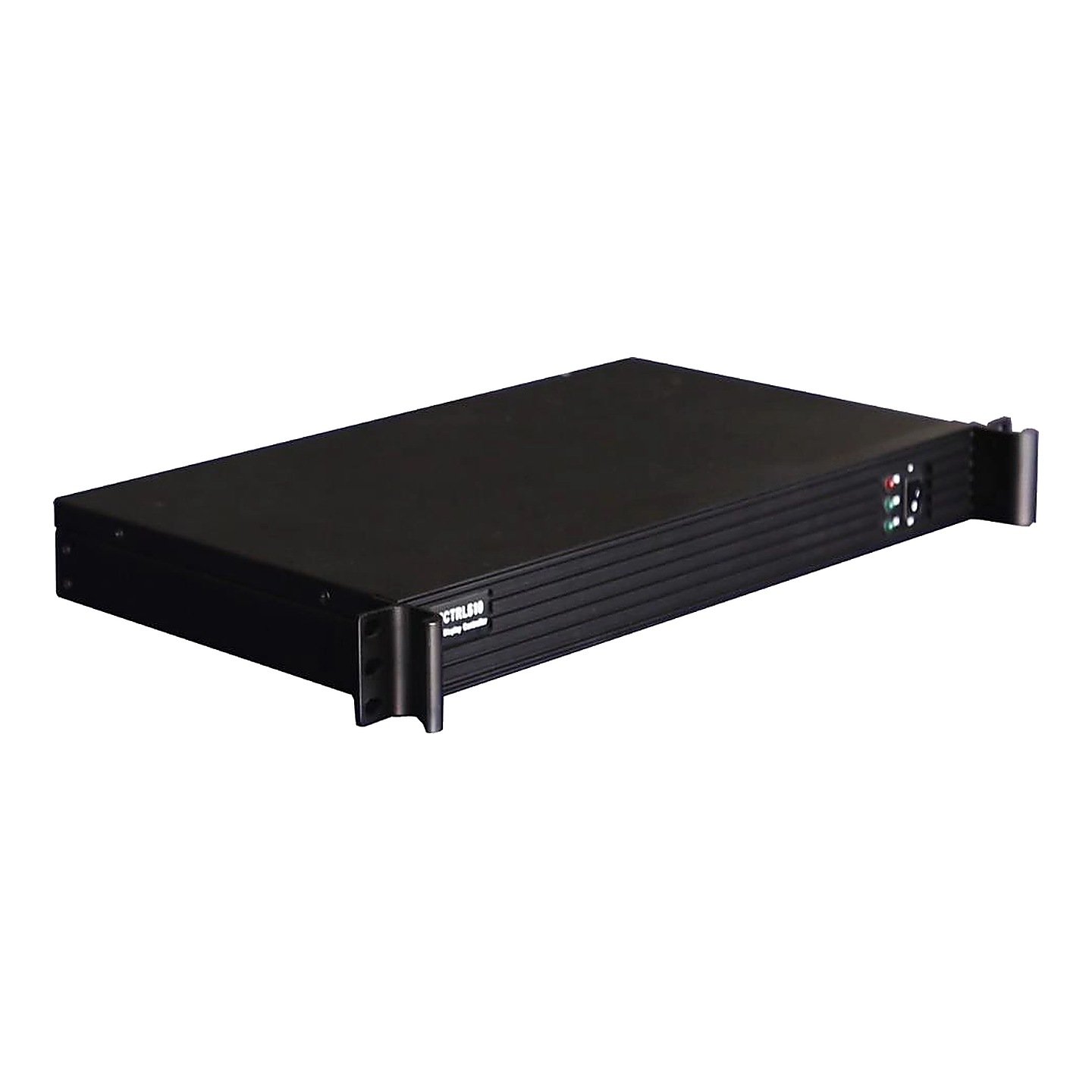
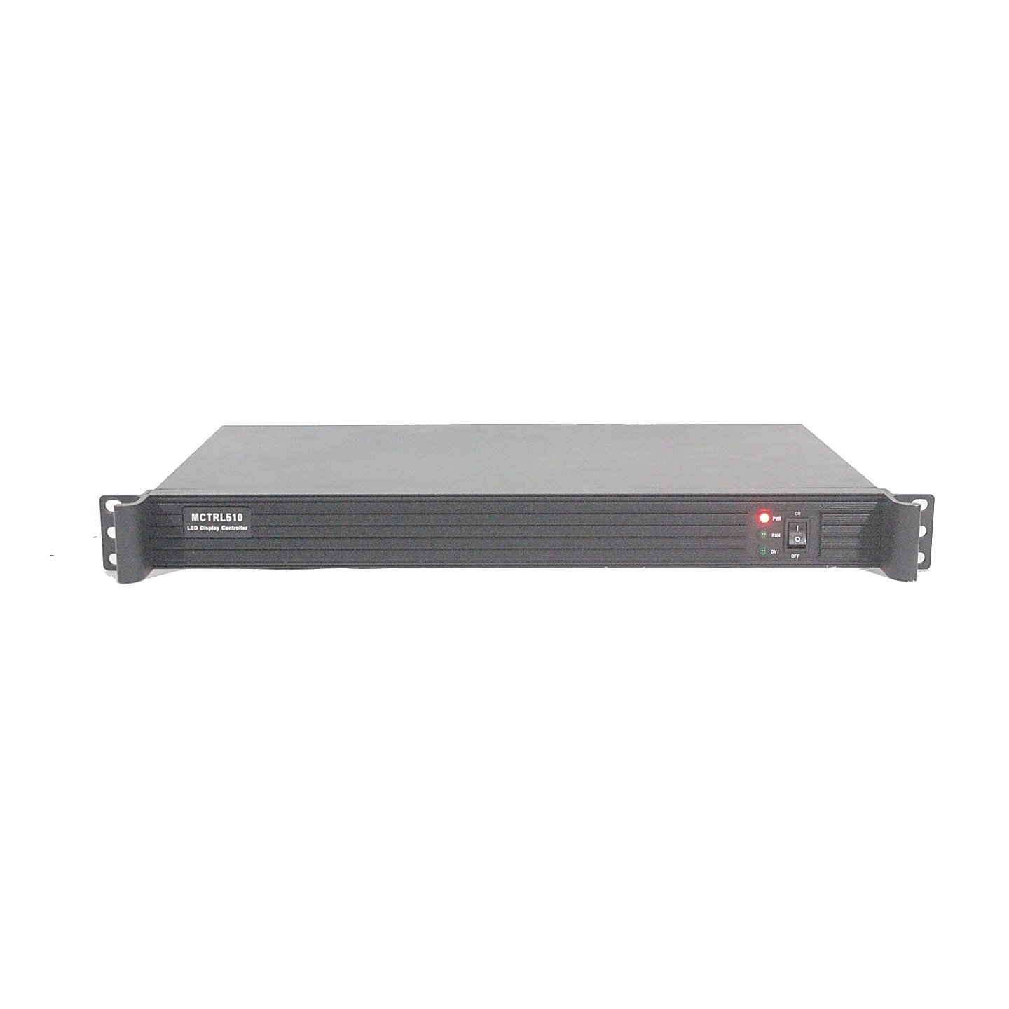
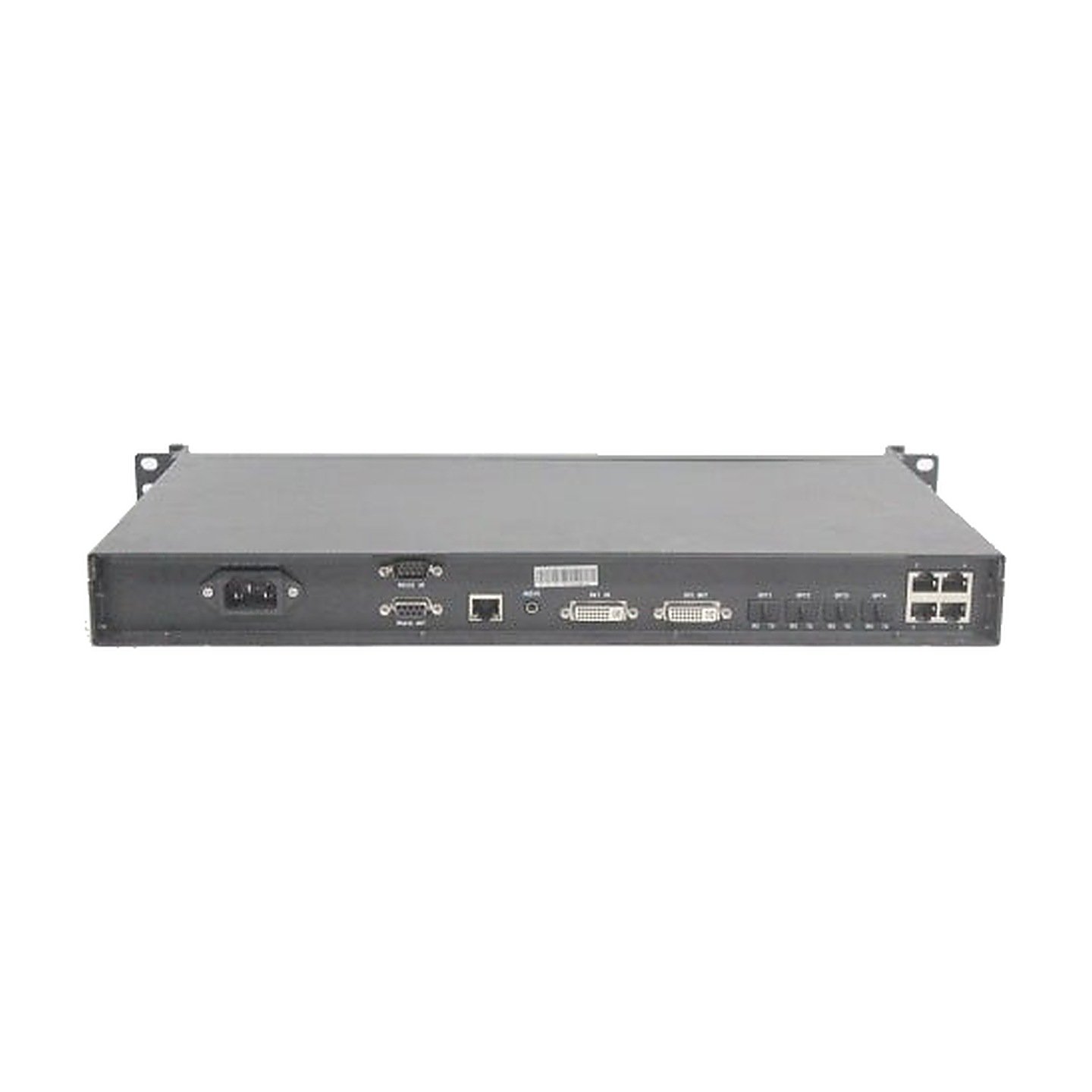
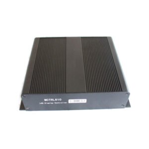
The NovaStar MCTRL510 is a legacy 1U LED sending controller built around a single DVI source. It sends the prepared image through four LED Ethernet outputs or four onboard optical outputs, provides a DVI loop output, and uses RS232 for controller cascading. A separate 100Mbps TCP/IP communication port lets a service computer reach the controller over a network.
The MCTRL510 is most relevant as an exact replacement in an existing system. Its current V1.0.0 document does not list HDMI, scaling, source switching, PIP, or video layers, so a computer, media server, or upstream video processor must prepare the DVI canvas before it reaches the controller.
Is the NovaStar MCTRL510 a current controller or a legacy replacement?
The MCTRL510 should be treated as a legacy replacement, and many current listings are used equipment, rental inventory or replacement stock. That does not make every remaining unit unusable. It means the buying decision should begin with the installed system, not with a list of features.
Choose the exact MCTRL510 when an existing rack, interactive floor, software integration, RS232 chain or optical receiver system depends on this model. For a new LED wall, a current controller will usually offer easier source compatibility and a clearer software path. Before buying new-old stock, confirm the unit condition, firmware, included accessories and warranty.
MCTRL510 load capacity: 2048×1152 or 1920×1200
NovaStar's V1.0.0 specification lists two maximum supported resolutions: 2048×1152 and 1920×1200. Those canvases contain 2,359,296 and 2,304,000 pixels respectively. The document does not support the 2.6-million-pixel total used on several reseller pages.
| Example canvas | Total pixels | Initial MCTRL510 check |
|---|---|---|
| 1920×1080 | 2,073,600 | Within the documented maximum canvas |
| 1920×1200 | 2,304,000 | One of the two documented maximum resolutions |
| 2048×1152 | 2,359,296 | Highest documented total |
| 2560×1024 | 2,621,440 | Above the documented total; do not approve from “2.6M” marketing copy |
The official document does not provide per-port pixel limits, custom-timing rules, or a refresh-rate table. Verify the actual port map in the controller configuration instead of importing limits from another MCTRL model.
MCTRL510 specifications
The table below stays within the MCTRL510 V1.0.0 document. Missing modern details are marked as checks rather than filled with nearby-model data.
| Specification | MCTRL510 |
|---|---|
| Video input | 1× DVI IN |
| Video loop/monitor | 1× DVI OUT |
| Audio | 1× audio input |
| LED data outputs | 4× Ethernet outputs or 4× optical-fiber outputs |
| Maximum supported resolution | 2048×1152 or 1920×1200 |
| Controller cascading | RS232 IN and RS232 OUT |
| Computer communication | 1× 100Mbps Ethernet port using TCP/IP |
| Documented device address | 192.168.11.2; subnet mask 255.255.255.0; gateway 192.168.11.1; port 6000 |
| Input power | AC 100–240V, 50/60Hz |
| Power consumption | 16 W |
| Operating temperature | –20°C to +60°C |
| Operating humidity | 0%–95% RH |
| Rack size | 19-inch 1U |
| Net weight | 2.9 kg |
| Fiber connector, wavelength and distance | Not specified in V1.0.0; verify against the existing optical receiver system |
| Current lifecycle | Legacy model; verify actual stock, condition and support |
Use the MCTRL510 datasheet PDF when matching rear-panel ports, network values, power and rack requirements.
MCTRL510 Ethernet, optical and TCP/IP control ports explained
The MCTRL510 has three connections that look network-related but do different jobs.
The four OUT ports carry LED data to receiving cards. The four OPT ports provide the optical output path. NovaStar describes the controller as using four Ethernet outputs or four optical outputs; the document does not present them as eight separate canvases or provide enough detail to approve an unknown optical receiver.
The 100Mbps COMMUNICATION port is different. It uses standard TCP/IP for communication with a PC and has the documented address 192.168.11.2. It is not a fifth LED data output. The service computer must be able to reach the 192.168.11.x subnet without taking the controller's address.
Only the communication port belongs on the control LAN. The LED OUT ports carry NovaStar display data and should not be routed through a normal office Ethernet switch.
MCTRL510 DVI loop-through and RS232 controller cascading
DVI OUT passes the incoming video signal to another controller or to a monitor. In a multi-controller rack, the first MCTRL510 receives the prepared DVI canvas and passes that video onward through the loop output.
RS232 IN and OUT handle controller-control cascading. They do not carry the video image and do not replace the DVI loop. A multi-unit system may need both paths: DVI for the source signal, then RS232 for coordinated control.
MCTRL510 setup and replacement checks
For an existing MCTRL510 replacement, record the complete rear-panel wiring before removing the old unit. Confirm whether the screen uses the four copper LED outputs or the four optical outputs, identify every optical receiver or converter, note the DVI source timing, and save the current receiving-card and cabinet configuration if the system still communicates.
The source must provide a supported DVI canvas because the V1.0.0 document does not list scaling. If the source is HDMI, 4K, interlaced, or a different timing, use a proven converter or processor before the MCTRL510 rather than assuming a passive adapter will solve every format issue.
For software access, connect through the dedicated communication LAN and confirm the controller at its documented address of 192.168.11.2. The MCTRL510 belongs to an older NovaLCT-era system, so verify the NovaLCT version and driver path before updating firmware or overwriting a working configuration. Once connected, load the correct receiving-card file, map the cabinets in their physical cable order, send the configuration, and test the entire wall before saving changes.
When optical outputs are involved, test with the actual fiber, receiver hardware, and spare path. A newer controller with 10G optical ports is not automatically compatible with a legacy MCTRL510 optical receiver.
MCTRL510 applications in existing LED systems
Exact replacement in a DVI rack
The MCTRL510 fits when the existing source, DVI loop, RS232 control chain, and cabinet map already depend on the same controller.
Interactive LED floors
Several installed interactive-floor systems and show-control tools still reference the MCTRL510. In those systems, compatibility with the touch-control software and network settings can matter more than adding newer video inputs.
Legacy onboard-fiber systems
Four optical outputs can preserve an existing long-distance data path when the matching receiver hardware is known and working. Do not approve a replacement from connector count alone.
Rental and fixed systems kept in service
An operator may keep a documented MCTRL510 as a tested spare for an older fleet. Labeling, firmware discipline, saved configurations, and known-good cabling are more valuable here than broad new-system claims.
MCTRL510 manual, datasheet, firmware and NovaLCT resources
The official regional download index shows MCTRL510 firmware V4.4.0.6, but use it only after the exact package and release notes have been verified. Never install MCTRL500, MCTRL600, MCTRL510 Pro, or another model's firmware on the MCTRL510.
Firmware download: MCTRL510 firmware package. Match it to the exact hardware version, save the working configuration and read the release notes before updating.
Direct PDF links: MCTRL510 User Manual PDF · MCTRL510 Datasheet PDF
MCTRL510 vs MCTRL500 and MCTRL600 replacement paths
The correct replacement depends on whether the old system needs the MCTRL510's control LAN or its onboard optical path.
| Replacement situation | Best path | Reason |
|---|---|---|
| Existing rack needs the exact 100Mbps TCP/IP control port and known MCTRL510 optical workflow | MCTRL510 | Exact-model compatibility may outweigh lifecycle age; verify stock, firmware and receiver hardware |
| Legacy DVI system needs four Ethernet/optical pairs but not MCTRL510 network control | MCTRL500 | Similar DVI, RS232 and four-port/four-optical architecture; still a legacy choice and not a guaranteed drop-in |
| New or rebuilt four-port system needs HDMI as well as DVI and does not need onboard legacy optical outputs | MCTRL600 | Current-style HDMI/DVI input, four Ethernet outputs, USB/NovaLCT control and a clearer support path |
| New system needs scaling, switching or layers | Video processor | Prepares the canvas and may combine processing with LED sending |
Do not select a replacement only from total resolution. The MCTRL510's unusual value is its transport and control interface mix; changing that mix may require a new fiber converter, receiver, network or source design.
Is the MCTRL510 right for your LED system?
The MCTRL510 is a sensible choice when the project specifically needs an exact legacy replacement: one DVI source, the same optical or Ethernet output path, RS232 cascading, and the 192.168.11.2 TCP/IP control workflow. It can also be useful as a tested spare for a known fleet.
For a new build, start with the source and transport requirements. The MCTRL600 is easier when HDMI input and four copper outputs are enough. If the system needs modern fiber, SDI, Genlock, more capacity, or built-in processing, choose a controller or processor designed for that workflow instead of adapting a legacy MCTRL510 around it.
Before ordering, verify the model label, unit condition, firmware, source resolution, optical receiver, fiber type, cabinet file, output assignment, control IP and RS232 chain. Those checks determine whether the unit is a true replacement.
MCTRL510 frequently asked questions
Is the MCTRL510 discontinued?
The model is treated as legacy in current catalogs. Remaining inventory may be new-old stock or used equipment, so confirm condition, warranty, firmware and included accessories before purchase.
How many pixels can the MCTRL510 control?
The official V1.0.0 document lists maximum resolutions of 2048×1152 and 1920×1200. The higher of those contains 2,359,296 pixels. It does not document a 2.6-million-pixel canvas.
Does the MCTRL510 have eight LED outputs?
Do not count the four Ethernet and four optical connectors as eight independent outputs. The document describes four Ethernet outputs or four optical outputs and gives no eight-channel combined mode.
Does the MCTRL510 have HDMI input or scaling?
Neither HDMI nor scaling is listed. The documented source is DVI, and the source or upstream processor should provide the final canvas.
What is the MCTRL510 100Mbps Ethernet port used for?
It is a TCP/IP communication port for the control computer. Its documented device address is 192.168.11.2. It does not send another cabinet chain.
Can the four LED Ethernet outputs connect through a normal network switch?
No. They use RJ45 connectors but carry LED display data, not ordinary office-network traffic. Use the dedicated communication port for TCP/IP control.
What is the difference between DVI OUT and RS232 OUT?
DVI OUT passes the video source to another device. RS232 OUT passes controller-control communication to the next unit in a cascade.
Which software configures the MCTRL510?
MCTRL510 systems use the NovaLCT generation of configuration tools, but version support should be confirmed before changing a working legacy system. Keep a backup of the receiving-card and screen configuration.
Is MCTRL510 firmware available?
NovaStar's regional download index lists MCTRL510 firmware V4.4.0.6. Use only a package verified for the exact MCTRL510 and read its release notes before updating.
Confirm the MCTRL510 hardware path before ordering
For a replacement check, provide photos of the model label and rear panel, current firmware if readable, DVI source resolution, LED canvas, receiving-card model, saved RCFG/RCFGX file, cabinet order, copper or optical output choice, optical receiver/converter model, fiber connector and distance, control-computer network settings, and the number of RS232-cascaded units. LED Control Depot can then confirm whether an MCTRL510 is appropriate or recommend a safer current-system replacement.
Reviews
There are no reviews yet.