
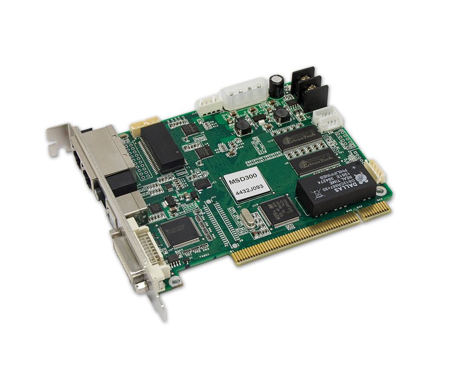
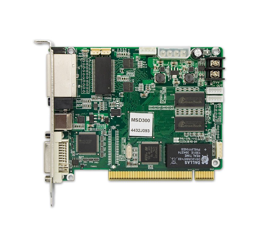
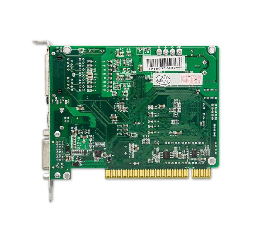
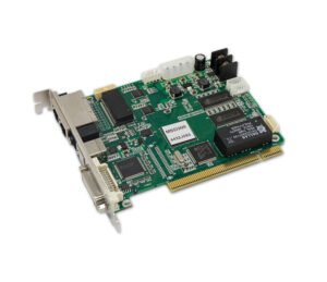
The NovaStar MSD300 is a bare sending card for a synchronous LED display system. It accepts one single-link DVI source and sends the prepared image to the LED wall through two Gigabit Ethernet outputs, with up to 1.3 million pixels in normal two-port loading.
Unlike an external controller box, the MSD300 does not include an enclosure or AC power inlet. It must be installed in a compatible host or powered sending-card enclosure that provides the correct mounting and regulated DC power.
What is the NovaStar MSD300 sending card?
The MSD300 sits between a video source and the receiving cards inside the LED cabinets. A computer, media server, or upstream processor prepares the final image and sends it to the card by DVI. The MSD300 maps that image across its two LED data outputs.
It is not a video processor or media player. NovaStar documents one single-link DVI input, not HDMI or SDI, and the current specification does not list built-in scaling, source switching, or layered composition. If the source cannot produce the required DVI canvas, place a suitable video processor before the card or choose a controller that includes the required front-end processing.
MSD300 host, power and installation requirements
Check the host before ordering the card. A complete installation needs:
- A chassis, processor, PC, or sending-card enclosure designed to hold the MSD300 safely.
- A regulated DC supply between 3.3 V and 5.5 V. NovaStar rates the card at 0.6 A and 3 W.
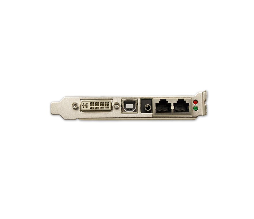
- Access to the DVI, USB Type-B, audio, and Ethernet connectors required by the project.
- Enough clearance and the correct mounting hardware for a 130.1 x 99.7 x 14.0 mm circuit board.
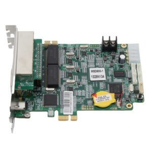
Do not assume that a normal PCI or PCIe slot will power or operate the MSD300. The NovaStar drawing labels the power connectors separately from the card's PCI-form gold fingers, and the specification calls for an external 3.3-5.5 V DC supply. Confirm the host's mounting, power cable, voltage, and connector access with the enclosure or equipment manufacturer.
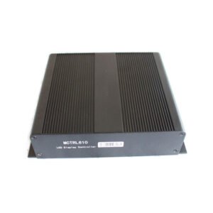
If the project does not already have a suitable host, the MCTRL300 is often the simpler choice because it places a similar DVI and two-port sending workflow inside a finished AC-powered box.
Why MSD300 1920×1200 input does not mean a 1920×1200 LED load
Start with the finished LED canvas, not the source computer's desktop resolution. Multiply the LED wall's pixel width by its pixel height. The normal two-port load must stay within 1,300,000 pixels, and no single Ethernet output can carry more than 650,000 pixels.
A 1280 x 720 wall contains 921,600 pixels, so it fits the total capacity. The cabinets still need to be divided between the two outputs so that each port remains below 650,000 pixels.
A 1920 x 1080 wall contains 2,073,600 pixels, so it does not fit one MSD300. This is true even though the DVI input accepts source timings up to 1920 x 1200@60Hz. Input timing describes the video signal the card can receive; loading capacity describes how many LED pixels it can send.
The same rule applies to custom wide or tall input timings. A supported source timing does not raise the 1.3-million-pixel LED limit.
The two Ethernet outputs can also be configured for redundancy. In that arrangement, one path backs up the other. Redundancy improves signal resilience, but the backup port does not add more screen capacity.
NovaStar MSD300 specifications
The figures below follow NovaStar's MSD300 Sending Card Specifications V2.4.2.
| Specification | NovaStar MSD300 |
|---|---|
| Product type | Internal LED sending card |
| Video input | 1x single-link DVI |
| Audio input | 1x audio connector |
| Maximum standard input | 1920 x 1200@60Hz |
| Custom source-timing limits | Up to 3840 x 600@60Hz wide or 548 x 3840@60Hz tall |
| Input format | 8-bit RGB 4:4:4 |
| Interlaced input | Not supported |
| LED data outputs | 2x Gigabit Ethernet RJ45 |
| Loading capacity | Up to 650,000 pixels per port; 1.3 million pixels in normal two-port loading |
| Ethernet redundancy | Supported between the two outputs |
| Computer control | USB 2.0 Type-B |
| Card cascading | UART IN/OUT; up to 20 cards |
| Light sensor | 1x connector for compatible automatic-brightness workflows |
| Calibration support | Pixel-level brightness and chroma calibration with the required NovaStar calibration system |
| Power input | DC 3.3-5.5 V |
| Rated current | 0.6 A |
| Rated power consumption | 3 W |
| Dimensions | 130.1 x 99.7 x 14.0 mm |
| Net weight | 104.3 g |
| Operating environment | -20°C to +75°C; 10%-90% RH, non-condensing |
| Included accessories | USB cable and DVI cable |
How the MSD300 connects from a DVI source to LED cabinets
The signal chain has four separate jobs:
- Prepare the image. A graphics card, media server, or upstream processor creates a progressive DVI signal within the MSD300's supported timing.
- Power and control the card. The host supplies regulated 3.3-5.5 V DC power. A USB Type-B cable connects a configuration computer to the MSD300 when the screen is being set up.
- Send LED data. The two RJ45 outputs carry mapped LED data to the receiving cards in the cabinets. They are not general-purpose LAN ports.
- Drive the modules. The receiving cards use the saved cabinet configuration to drive the LED modules and reproduce the mapped image.
The audio connector is available when the control system includes a compatible NovaStar audio path. UART IN and OUT can cascade up to 20 MSD300 cards for control, but cascading does not automatically combine all of their output ports into one unplanned screen. Each card and cable path still needs a defined portion of the display.
MSD300 setup with NovaLCT
Use NovaLCT to configure the card and the receiving cards over USB. The exact receiver parameters depend on the LED modules and cabinet wiring, so begin with the known-good RCFG or RCFGX file supplied by the screen manufacturer whenever possible.
A safe commissioning order is:
- Confirm the host mounting and regulated 3.3-5.5 V power before connecting the LED data cables.
- Connect the prepared DVI source and link the configuration computer to the MSD300 by USB.
- Open NovaLCT and confirm that the card, input signal, and receiving cards are detected.
- Load the correct receiving-card or cabinet configuration for the installed modules.
- Map the cabinets in their real cable order and keep each Ethernet output within 650,000 pixels.
- Save the configuration, then test cabinet order, solid colors, grayscale, signal loss, and any planned redundant path.
The receiving-card file must match the exact cabinet electronics. Pixel pitch alone cannot tell you the scan type, module dimensions or data-group order. If the original file is missing, stop before writing new receiver settings: identify the receiving card, module wiring and driver arrangement, then rebuild and test the configuration with one cabinet before sending it across the full screen.
MSD300 manual, datasheet, software and firmware
Use the MSD300 datasheet PDF for the official connector, power, dimension, and loading values. The current file is a specification sheet, not a complete step-by-step user manual.
For screen programming, use the MSD300 setup manual, which hosts the genuine Nova M3 system instructions that name the MSD300, together with the cabinet maker's RCFG or RCFGX file. The page labels it as a system manual because NovaStar's reviewed archive does not provide a separate MSD300 hardware manual. Download NovaLCT from the maintained software page rather than relying on a version number copied into evergreen product text.
Firmware should come from NovaStar's current model-support destination or a verified internal download. Before updating a working card, confirm the exact model, installed version, release notes, and approved update process. MSD300 and MSD300-1 are separate models and should not be treated as the same firmware target without explicit documentation.
Firmware download: MCTRL300 / MSD300 family firmware package. This is a family firmware package, not a model-only file. Confirm the hardware revision, save the working configuration and read the release notes before updating.
Direct PDF links: MSD300 User Manual PDF · MSD300 Datasheet PDF
MSD300 applications
The MSD300 makes the most sense when the project is designed around an internal sending card:
Powered sending-card enclosures: compact boxes built to supply the correct DC power and expose the card's front connectors.
OEM processors and control equipment: integrated systems with a supported card bay, mechanical mounting, and wiring already planned.
Existing MSD300 replacements: service work where the old system already provides the correct power, host space, and connector access.
Embedded fixed installations: signs or LED control systems where the sending hardware is built into a protected equipment chassis rather than placed in a separate controller box.
The venue alone does not decide whether the MSD300 fits. A retail display, stage, monitoring wall, or sports screen can use many kinds of controller. The decisive questions are whether the wall fits the card's load limits and whether the equipment provides the correct host and power arrangement.
Is the MSD300 right, or should you choose MSD300-1 or MCTRL300?
The three models serve a similar DVI and two-port capacity class, but their physical form and connector sets are different.
| Model | Choose it when | Check before ordering |
|---|---|---|
| MSD300 | The host is designed for the original internal card and the system uses its audio connection | Confirm 130.1 x 99.7 x 14.0 mm fit, regulated 3.3-5.5 V power, and the exact host cable |
| MSD300-1 | The equipment is designed for the newer card form factor and does not require the MSD300 audio input | Its 138.8 x 120.6 x 22.0 mm board is larger; do not assume it is a physical drop-in replacement |
| MCTRL300 | You want a finished external controller with its own AC inlet and enclosure | It is easier to deploy, but it occupies external equipment space rather than an internal card bay |
Choose the MSD300 when the system already supports its exact card form factor and the LED wall fits within the two-port limits. If the host is uncertain, an external controller is usually easier to specify. If the project needs HDMI or SDI, more than 1.3 million pixels, built-in scaling, or source switching, compare the wider NovaStar controller range before deciding.
MSD300 frequently asked questions
Is the MSD300 a PCIe card?
Do not treat it as a normal PCIe expansion card without host documentation. The board uses PCI-form gold fingers for its host arrangement, but NovaStar separately specifies DC 3.3-5.5 V power and does not describe standard PCIe data operation in the current specification. Confirm the exact enclosure, power cable, and mounting system.
Can I install the MSD300 in a normal desktop PC?
Only when the PC or adapter system is specifically prepared to mount and power the card correctly. An empty slot alone is not enough evidence. Check regulated DC power, mechanical clearance, bracket alignment, cable access, and the host manufacturer's instructions.
Does the MSD300 have HDMI input or built-in scaling?
NovaStar documents one single-link DVI input. The current specification does not list HDMI input or built-in scaling. A compatible HDMI-to-DVI connection may carry a digital source signal, but it does not add scaling or source switching. The source still has to produce a supported progressive timing.
Why does the MSD300 accept 1920 x 1200 but load only 1.3 million pixels?
These numbers describe different stages. The first is the video timing the DVI input can receive. The second is the number of LED pixels the two Ethernet outputs can send. A source canvas can therefore be larger than the active LED area, but the mapped LED load must remain within 1.3 million pixels and 650,000 pixels per port.
Can one MSD300 Ethernet port back up the other?
Yes. NovaStar documents redundancy between the two Ethernet outputs. When one path backs up the other, the backup does not add screen capacity. Plan the primary load so the redundant path can carry the same mapped screen area.
What software configures the MSD300?
Use NovaLCT for standard sending-card, receiving-card, and screen-connection setup. The correct cabinet configuration remains just as important as the software: use the screen maker's known-good RCFG or RCFGX file whenever it is available.
Confirm your MSD300 host and LED wall before ordering
Send us the host or enclosure model, available power voltage, card-bay dimensions, source format, full LED canvas, cabinet pixel size, receiving-card model, and planned cable order. We can check whether the MSD300 fits both the equipment and the screen, or recommend an external controller when that will make installation simpler.
Reviews
There are no reviews yet.