
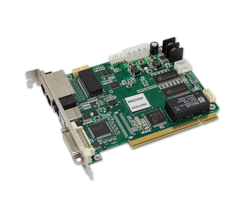
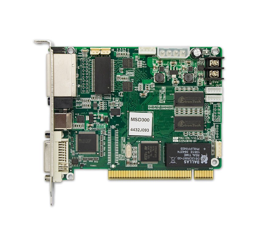
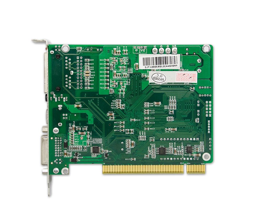
The NovaStar MSD300-1 is an internal sending card for a compatible desktop PC or controller chassis. It accepts one 8-bit single-link DVI source, sends LED data through two RJ45 outputs, and connects to NovaLCT through USB. Its maximum LED load is 1,300,000 pixels, with up to 650,000 pixels on each output.
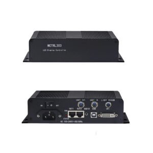
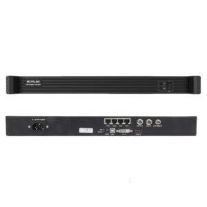
This card needs a conventional full-height PCI host and DC power within 3.3–5.5V. It is not a PCIe graphics card, and the host slot does not replace the DVI or USB cables. If you need the same two-port sending capacity without installing a card inside a computer, the standalone MCTRL300 is usually easier to integrate.
What is the NovaStar MSD300-1?
The MSD300-1 turns a prepared DVI image into NovaStar LED data. The graphics card or upstream processor creates the final source frame, the MSD300-1 maps the active LED area across its two outputs, and the receiving cards inside the cabinets drive the modules.
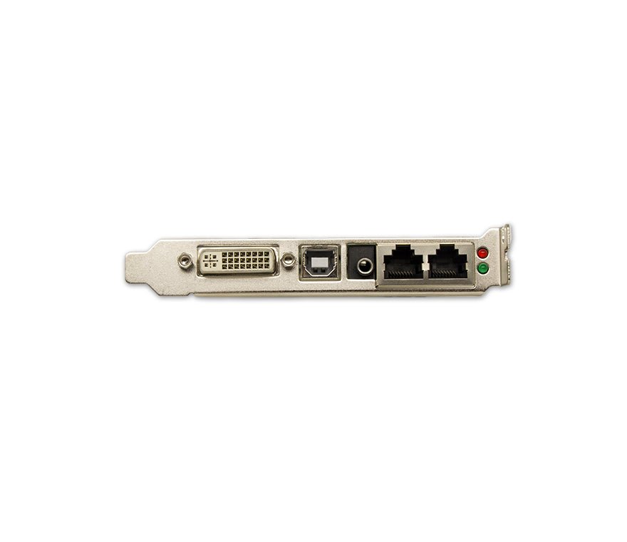
Three separate connections are required even when the sending card sits inside the same computer. DVI carries the image, USB carries configuration commands, and the two RJ45 outputs carry data to the LED wall. The classic PCI edge holds the card in a compatible host and participates in its power arrangement; it is not the video or NovaLCT communication path.
The MSD300-1 has no external audio connector. Use it when audio is handled elsewhere; it is not an audio replacement for the original MSD300.
MSD300-1 PCI host and power requirements
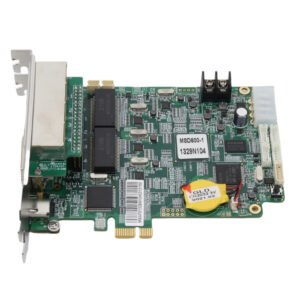
Check the host before ordering the card. The MSD300-1 uses classic PCI gold fingers and a full-height bracket. It does not fit a PCIe-only motherboard, and its 138.8 × 120.6 × 22.0 mm board needs enough case and adjacent-slot clearance.
The card requires DC 3.3–5.5V, draws 0.6A at its rated condition and uses about 3W. Confirm that the computer, processor chassis or approved power connector provides the correct voltage and pinout. Do not connect 12V, an AC power cord or an improvised supply simply because the plug appears to fit.
The official appearance diagram shows both PCI gold fingers and board-level power connectors, but the specification does not give a universal wiring method for every host. If the card is going into a video processor or custom chassis, verify that chassis's approved MSD300-1 slot and power harness.
The V1.1.0 document lists no product certifications. If the project requires FCC, EMC, RoHS or another regional certificate, confirm acceptable documentation before specifying the card. The original MSD300 or an enclosed MCTRL300 may be a better path when certification paperwork is required.
Can the MSD300-1 drive your LED wall?
The input frame and the LED wall are not the same limit. The MSD300-1 can accept a 1920×1200@60Hz DVI signal, but it can map only 1,300,000 LED pixels in total and no more than 650,000 pixels to either output.
| Example LED canvas | LED pixels | Initial fit check |
|---|---|---|
| 1280×960 | 1,228,800 | Within total load; split both output chains below 650k each |
| 1600×800 | 1,280,000 | Within total load; verify the port map carefully |
| 3840×300 | 1,152,000 | Within the custom-width and total-load limits |
| 500×2500 | 1,250,000 | Within the custom-height and total-load limits |
| 1920×1080 | 2,073,600 | Above the 1.3M LED load even though the input timing is accepted |
| 1920×1200 | 2,304,000 | Valid source frame, but too many active LED pixels for one card |
Wide and tall source timings are supported up to 3840×600@60Hz or 548×3840@60Hz. Those timing limits do not cancel the LED-load limits. A wide source may contain black or unused area while the mapped LED cabinets stay below 1.3M.
The DVI input supports 8-bit RGB 4:4:4 progressive video. Interlaced input is not supported, so convert 1080i or another interlaced source to progressive before it reaches the card.
NovaStar MSD300-1 specifications
The table below uses the exact MSD300-1 V1.1.0 specification instead of data borrowed from MSD300 or MCTRL300.
| Specification | MSD300-1 |
|---|---|
| Product type | Internal LED display sending card |
| Host interface | Classic PCI gold fingers; full-height bracket |
| Video input | 1× single-link DVI |
| Input format | 8-bit RGB 4:4:4 |
| Maximum standard input | 1920×1200@60Hz |
| Custom input width | Up to 3840 pixels, for example 3840×600@60Hz |
| Custom input height | Up to 3840 pixels, for example 548×3840@60Hz |
| Interlaced video | Not supported |
| LED data outputs | 2× RJ45 Gigabit Ethernet |
| Total LED load | Up to 1,300,000 pixels |
| Load per output | Up to 650,000 pixels |
| Output redundancy | Supported between the two Ethernet outputs |
| Computer control | 1× Type-B USB 2.0 |
| Device cascading | UART IN/OUT; up to 20 devices |
| Light sensor | 1× connector |
| Audio input | None documented |
| Input voltage | DC 3.3–5.5V |
| Rated current / power | 0.6A / 3W |
| Operating temperature | –20°C to +75°C |
| Operating humidity | 10%–90% RH, non-condensing |
| Dimensions | 138.8 × 120.6 × 22.0 mm |
| Net weight | 104.3g |
| Certifications in V1.1.0 | None |
| Listed accessories | 1× USB cable and 1× DVI cable |
Use the MSD300-1 datasheet PDF to check the card drawing, connector labels, dimensions and electrical limits before choosing a host.
MSD300-1 DVI, USB, UART and Ethernet connections explained
The DVI connector receives the image from the computer's graphics card or an upstream processor. It accepts single-link DVI, so an HDMI-only source may need a proven adapter or processor that outputs a supported progressive RGB timing.
The Type-B USB port connects the card to the computer running NovaLCT. USB is the control path used to detect the sender, load the receiving-card configuration and map the screen. Installing the PCB in a PCI slot does not remove this USB requirement.
The two RJ45 ports send NovaStar LED data to the first receiving card in each cabinet chain. Although they use network-style connectors and cable, they are not normal office Ethernet ports and should not be routed through an ordinary network switch.
UART IN and OUT let NovaLCT control several sending cards as a group. UART does not carry the DVI image and does not add LED capacity on its own. Each card still needs a valid video source and its own mapped output chains.
Automatic brightness is available only after a compatible sensor has been connected and set up in the control software. Pixel-level brightness and chroma calibration require the wider NovaStar calibration workflow, including compatible receiving cards, measurements and calibration software.
MSD300-1 installation and NovaLCT setup
Shut down the host and disconnect power before installing the card. Confirm that the slot is conventional PCI, not PCIe, and that the bracket and board clear the case. Seat the card securely, fasten the bracket and connect only the approved 3.3–5.5V power path for that host.
Connect the graphics output to the MSD300-1 DVI input and connect the Type-B USB port to the service computer. Run each RJ45 output directly to the first receiving card in its assigned LED chain. Add the light sensor or UART cascade only when the design calls for it.
In NovaLCT, confirm that the sending card appears over USB before changing the screen. Load the correct receiving-card RCFG or RCFGX file, set the source timing, map the cabinets in their real cable order, send the configuration to hardware and test every chain. Save a known-good copy of the receiving-card and screen-connection files before closing the job.
If the source is interlaced, outside the supported DVI timing or not 8-bit RGB 4:4:4, correct it at the graphics card or place a suitable video processor before the sender. Do not use NovaLCT mapping as a substitute for source conversion.
MSD300-1 Ethernet redundancy and multi-card cascading
The two Ethernet outputs can carry separate LED chains for the full 1.3M-pixel capacity, or they can be configured as a redundant pair. In a redundant design, both ports protect the same receiving-card path, so the protected LED load must fit within one 650,000-pixel output. Do not count a backup port as additional active capacity.
Up to 20 MSD300-1 units can be linked through UART for coordinated control. That does not create one twenty-card video input. Plan how every card receives the source image, how the canvas is divided, and which LED cabinets belong to each output. The MSD300-1 does not provide a DVI loop output, so a multi-card system may need a graphics card with multiple outputs or an external DVI distribution path.
Use redundancy when signal continuity matters more than maximum two-port capacity. Use multiple active cards when the wall exceeds 1.3M pixels, then verify each card's source timing and port map separately.
MSD300-1 applications in integrated LED systems
LED control PC with a legacy PCI slot
The card keeps DVI input, USB configuration and two LED outputs inside one serviceable desktop when the motherboard and power path are known.
Compatible processor or sender-card chassis
Some integration chassis accept internal sending cards. Confirm the exact PCI slot, bracket, voltage and harness instead of assuming every processor fits the MSD300-1.
Exact MSD300-1 replacement
The safest replacement keeps the same host, DVI source, USB control, cabinet map and receiving-card firmware. Save the existing configuration before swapping hardware.
Compact wide or tall LED canvas
Custom DVI timings can suit ribbon or portrait displays, provided the active LED canvas remains below 1.3M total and both output chains stay below 650k.
MSD300-1 manual, datasheet, NovaLCT and support resources
The MSD300-1 datasheet PDF is the verified V1.1.0 source for capacity, inputs, outputs, power, dimensions and environment. It provides the exact-model specification table needed to check power, size and operating limits.
NovaLCT is the configuration tool for connecting to the sending card over USB, loading receiving-card files and mapping the LED screen. NovaCLB is relevant only when the project uses a complete pixel-level calibration workflow.
The MSD300-1 setup manual provides the official NovaLCT synchronous-system configuration guide. NovaStar's reviewed archive does not provide a standalone MSD300-1 hardware manual, so the page says exactly what the file is. The recent Manuals.plus file is not used because it incorrectly calls the card PCIe. No exact firmware package was verified in the local download inventory either, so do not display a firmware button until the file and release notes are matched to MSD300-1.
Firmware download: MCTRL300 / MSD300 family firmware package. This is a family firmware package, not a model-only file. Confirm the hardware revision, save the working configuration and read the release notes before updating.
Direct PDF links: MSD300-1 User Manual PDF · MSD300-1 Datasheet PDF
MSD300-1 vs MSD300 vs MCTRL300
All three products belong to the same general two-output, 1.3M-pixel class, but the installation decision is different.
| Decision point | MSD300-1 | MSD300 | MCTRL300 |
|---|---|---|---|
| Form factor | Internal classic-PCI sending card | Internal sending card | Standalone enclosed controller |
| Video input | 1× single-link DVI | 1× single-link DVI | 1× single-link DVI |
| External audio input | No | Yes | Yes |
| LED outputs | 2× RJ45 | 2× RJ45 | 2× RJ45 |
| Total load | 1.3M pixels | 1.3M pixels | 1.3M-pixel class |
| Computer control | Type-B USB | Type-B USB | Type-B USB |
| Power | DC 3.3–5.5V from compatible host/power path | DC 3.3–5.5V from compatible host/power path | AC 100–240V standalone supply |
| Official document certifications | None in V1.1.0 | EMC, RoHS, PFoS, FCC in V2.4.2 | Multiple certifications listed in current documentation |
| Best fit | Host-integrated video-only system | Host-integrated system that needs external audio or documented certifications | System without a suitable PCI host, or buyer who prefers an external box |
Choose MSD300-1 when the existing host is proven and audio is handled elsewhere. Choose MSD300 when the external audio connector or its current certification record matters. Choose MCTRL300 when you want the same basic sending role without depending on a conventional PCI slot and internal DC power.
None of these products adds source scaling, seamless switching or video layers. If the source workflow needs those functions, prepare the image with a graphics system or a suitable processor before the sender.
Is the MSD300-1 right for your system?
The MSD300-1 is a good fit when the host has a verified conventional PCI slot, full-height clearance and the correct low-voltage power path. The source must provide progressive 8-bit single-link DVI, the LED wall must stay below 1.3M pixels, and each data chain must stay below 650k.
It is also practical as an exact spare for a known fleet. Keep the firmware, NovaLCT version, receiving-card file and screen map with the spare so the card can be installed without rebuilding the system under pressure.
If the computer has only PCIe, the project requires documented certifications, the source needs HDMI or SDI, or the system should remain independent of a desktop motherboard, the MSD300-1 may not be the best option. The MCTRL300 is the closest standalone alternative, while a current processor/controller is better when scaling or switching is required.
MSD300-1 frequently asked questions
Is the MSD300-1 a PCI or PCIe card?
It uses classic PCI gold fingers and specialist distributors identify it as a conventional PCI card, not PCIe. Confirm the slot visually and from the motherboard manual before ordering.
Does the PCI slot carry the video signal?
No. Video enters through the external single-link DVI connector. NovaLCT communicates through Type-B USB, and the RJ45 outputs carry LED data.
How is the MSD300-1 powered?
The official specification requires DC 3.3–5.5V and lists 0.6A rated current with 3W rated consumption. Use only the approved slot or power harness for the host; never connect 12V or AC mains.
Can the MSD300-1 drive a 1920×1200 LED wall?
No. It can accept a 1920×1200 source frame, but the LED wall is limited to 1,300,000 active pixels. A 1920×1200 wall contains 2,304,000 pixels.
Can the MSD300-1 use a wide custom resolution?
Yes. The input can be configured up to 3840 pixels wide, for example 3840×600@60Hz, but the mapped LED area must still fit the 1.3M total and 650k-per-port limits.
Does the MSD300-1 support interlaced video?
No. Use a progressive source or convert the signal before the DVI input.
Does the MSD300-1 have an audio input?
No external audio connector is documented. The original MSD300 has an audio input.
Can both Ethernet outputs be used for backup?
Yes. Redundancy between the two ports is supported. When one port backs up the other, design the protected chain within one port's 650,000-pixel limit.
Does UART cascading increase the LED capacity?
Not by itself. UART coordinates control of up to 20 cards. Every card still needs its own source path and LED output assignment.
Is the MSD300-1 compatible with every NovaStar receiving card?
Do not rely on a blanket compatibility claim. Confirm the receiving-card model, firmware generation, RCFG/RCFGX file and cabinet design before ordering.
Which software configures the MSD300-1?
Use NovaLCT through the Type-B USB control connection. NovaCLB is added only for a full calibration workflow.
Is there an official MSD300-1 user manual or firmware download?
Use the exact-model V1.1.0 specification PDF for hardware facts and the MSD300-1 setup manual for the official NovaLCT configuration workflow. NovaStar's reviewed archive does not provide a separate MSD300-1 hardware manual or a verified exact firmware package.
Check the MSD300-1 host before ordering
Send photos of the motherboard slot, case bracket and existing power connector, along with the computer model, DVI source timing, LED canvas, pixels on each output, receiving-card model, RCFG/RCFGX file, NovaLCT version, redundancy plan and number of cascaded senders. LED Control Depot can then confirm whether the MSD300-1 fits the existing host or whether MSD300, MCTRL300 or another controller is the safer choice.
Reviews
There are no reviews yet.