
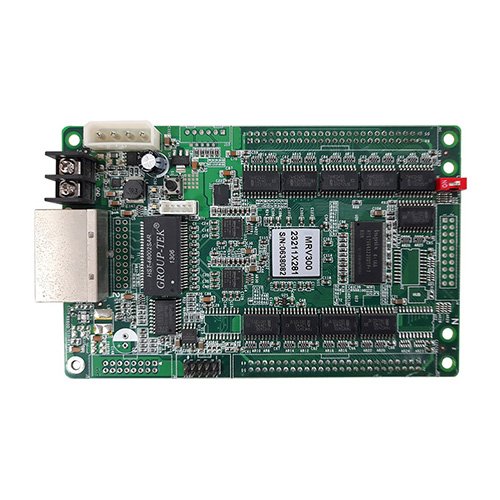
What is the NovaStar MRV300 receiving card?
The NovaStar MRV300 is an original, standalone Nova receiving card used in older LED cabinets and LED-bar layouts. It receives the image data sent to its cabinet and outputs that data in one of three documented forms: 16-group RGBR parallel data, 20-group RGB parallel data or 64-group serial data. Those modes are the reason to choose or replace the card; a maximum pixel number alone cannot show whether the cabinet wiring will work.
MRV300 also has separately named hardware variants, MRV300-1 through MRV300-4. They are not firmware versions and they are not interchangeable by name alone. The base MRV300 has its own official specification, so choose it only when the installed card and cabinet evidence identify the original base model.
MRV300 key features
Match the output to the cabinet, not the other way around
The original MRV300 can serve different wiring arrangements through RGBR parallel, RGB parallel or serial-data output. That flexibility helps an older cabinet or LED bar keep its designed signal path. It does not mean that a random receiving-card file can be applied to every MRV300 screen; the selected mode and cabinet wiring still have to match.
Keep a panel from becoming a black rectangle during a source interruption
The card supports a pre-stored picture. In a compatible cabinet, that image can be used when the normal source path is absent instead of leaving a dark patch in the wall. It is useful for a fixed display or a service check, but it should be set and tested while the cabinet is working rather than treated as an emergency substitute for a proper source and signal path.
Use cabinet signals to narrow a fault
The MRV300 can report temperature, Ethernet-cable communication status and supply voltage. It also supports configuration-file readback and pixel-level brightness/chromaticity calibration. Together, those functions help a technician identify whether a bad-looking cabinet needs a configuration restore, a cable/power inspection or a module-level repair.
NovaStar MRV300 specifications
These are the original MRV300 V2.1.1 facts. They describe the base card only; do not use them to identify the connector direction of an MRV300-1, -2, -3 or -4.
| Parallel output modes | 16-group RGBR or 20-group RGB |
|---|---|
| Serial output mode | 64 groups |
| Maximum resolution | 256 × 226 pixels |
| Rated voltage | 3.3 V minimum, 5.0 V typical, 5.5 V maximum |
| Rated current | 0.33 A minimum, 0.50 A typical, 0.55 A maximum |
| Working environment | −20°C to +70°C; 10% to 90% RH |
| Board thickness | About 1.6 mm; overall thickness about 18.5 mm |
| Compliance | EU RoHS and CE-EMC |
MRV300 output modes: RGBR, RGB and 64 serial data
The output mode determines what the cabinet expects from the card. For RGBR or RGB parallel wiring, the card sends groups of colour data to the matching cabinet interface. For serial mode, it provides 64 independent data lines for an LED-bar arrangement. The difference is physical and electrical, not a preference that can be changed after a replacement without checking the modules and wiring.
| Cabinet evidence | MRV300 mode to confirm | Why it matters before ordering |
|---|---|---|
| Module or hub drawing identifies 16-group RGBR | 16-group RGBR parallel data | The virtual R signal has a defined role in the original 1/32 scan arrangement. |
| Module or hub drawing identifies 20-group RGB | 20-group RGB parallel data | The data mapping differs from the RGBR arrangement even when the cabinet looks similar. |
| Horizontal or vertical LED-bar layout | 64-group serial data | Each serial line serves a bar location, so the original data order is part of the image. |
| No working card or cabinet record | Unknown | Do not guess the mode from pixel pitch; collect the module, hub and wiring information first. |
This mode check is especially important for older signage. A card may communicate with the system yet display garbled rows, missing sections or a shifted image when its output mode does not match the existing panel wiring.
MRV300 stored image and cabinet recovery
Before removing a working MRV300, use NovaLCT to read back its configuration file and save the working screen record. The configuration contains the cabinet’s scan, wiring and output-mode information. It is not interchangeable with a file from a different screen just because both use an MRV300 label.
After fitting a confirmed match, restore one cabinet first. Check the image order, brightness and colour before sending anything to the rest of the wall. If the normal source path is unavailable, the stored-picture function can assist with a controlled test, but an orderly restore still needs the correct receiving-card configuration and signal route.
MRV300 replacement compatibility
An MRV300 replacement decision needs the exact base-card label, the selected output mode, cabinet voltage and saved configuration. A 256 by 226 capacity figure does not identify which RGB or serial arrangement the cabinet uses. If the original card is no longer readable, take clear photos of the card and cabinet connections, note whether the display uses modules or LED bars, and keep any old configuration files with the service record.
For a quantity order or uncertain repair, send those details through our MRV300 compatibility request. The useful outcome is a verified match or a clear explanation of what must be checked next, not an arbitrary newer receiving card.
MRV300 vs MRV300-1, MRV300-2, MRV300-3 and MRV300-4
NovaStar’s original specific-model list identifies the suffixes by connector placement and gender. They are hardware descriptions. Order the exact printed suffix from the existing card; do not select one by assuming a later number is a newer version.
| Model | Official connector description | Order rule |
|---|---|---|
| MRV300 | Original base card with its own V2.1.1 specification | Confirm the original board and output mode; do not treat it as a suffix placeholder. |
| MRV300-1 | Male connector on top | Match the top-side male connection and cabinet mating side. |
| MRV300-2 | Male connector on bottom | Match the bottom-side male connection and cabinet clearance. |
| MRV300-3 | Female connector on top | Match the top-side female connection and cabinet pins. |
| MRV300-4 | Female connector on bottom | Match the bottom-side female connection and cabinet pins. |
MRV300 datasheet, firmware and NovaLCT
The MRV300 datasheet documents the base card’s output modes and specific-model list. NovaLCT is used to protect a working configuration before a repair. No exact public MRV300 firmware package was verified during this review, so the official download center is offered only for a confirmed hardware match, not as a generic update button.
NovaStar MRV300 FAQ
What does the MRV300 receiving card do?
MRV300 receives data for a compatible LED cabinet or LED-bar layout and outputs it as the cabinet’s configured RGBR, RGB or serial data path.
What is the MRV300 maximum resolution?
The original V2.1.1 specification lists a maximum of 256 by 226 pixels. Confirm the output mode and existing cabinet wiring as well as the pixel count.
What is the difference between MRV300 RGBR, RGB and serial modes?
They are different documented output arrangements. RGBR and RGB serve parallel module paths, while serial mode provides 64 independent data lines for LED-bar layouts. The original wiring decides which applies.
Can MRV300 show a stored image?
It supports a pre-stored picture in a compatible setup. Configure and test that image while the cabinet is working; it does not replace a correct source, cable path or configuration file.
Can MRV300-1 replace an original MRV300?
Not automatically. MRV300-1 has a top-side male connector. Compare the exact printed model, connection orientation and cabinet mating hardware before changing to a suffix model.
What should I save before replacing an MRV300?
Read back the working configuration with NovaLCT and store it with the cabinet records. It carries the output-mode, scan and wiring information needed for a controlled restore.
Why can the wrong MRV300 configuration scramble a screen?
A configuration designed for a different RGB/RGBR/serial arrangement can send data to the wrong locations. Test one confirmed cabinet before applying any file to a whole wall.
Can MRV300 help identify a cabinet fault?
It can monitor temperature, power-supply voltage and Ethernet-cable status. Use those checks with mapping and the cabinet record to narrow the problem before replacing multiple parts.
Where can I find MRV300 firmware?
No exact public MRV300 firmware package was verified during this review. Preserve a working configuration and use NovaStar’s download center only after the original card and output mode have been confirmed.
What should I send for an MRV300 replacement check?
Send the card label, clear front-and-back photos, cabinet wiring or hub photo, whether the display uses modules or LED bars, a saved configuration if available and the needed quantity through our compatibility request form.
Reviews
There are no reviews yet.