
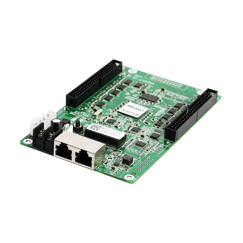
What is the NovaStar MRV300-4 receiving card?
The NovaStar MRV300-4 is a legacy LED receiving-card variant for an existing cabinet. It receives the prepared screen signal from the controller or the preceding cabinet, then passes the mapped pixel data to the LED modules through the cabinet’s matching interface. The important part of the model name is the suffix: MRV300-4 has female connectors on the bottom of the board.
That makes it a precise replacement choice. The bottom-side sockets must meet the cabinet’s matching pins in the same position. A card with the same capacity but a different connector side or gender can look almost identical on a workbench and still be impossible to install once the cabinet is open. Check the printed model, the side of the two mating points and the pins on the hub-board assembly before ordering.
The official MRV300 specification gives a maximum card load of 256 × 226 pixels. It is a useful ceiling for identifying the card, but it is not a promise that every cabinet can be redesigned around that figure. The module driver IC, scan pattern, existing wiring and saved configuration decide how the cabinet actually works.
MRV300-4 key features
Bottom-side female sockets for the matching cabinet pins
The MRV300-4 uses the same bottom-side placement as MRV300-2, but it has sockets rather than male headers. That difference is small in a catalogue and decisive inside a cabinet. It protects the buyer from choosing a nearby suffix simply because the board size and network connection appear familiar.
Three documented output arrangements for the original cabinet design
The MRV300 family supports 16-group RGBR parallel data, 20-group RGB parallel data or 64-group serial data. These are ways the original cabinet may have been wired; they are not three extra features to select after purchase. The hub board, modules and saved configuration determine which arrangement belongs to the screen.
Useful status checks when a cabinet fails
When used with a compatible cabinet, the card can support temperature, supply-voltage and Ethernet communication checks. It also supports calibration data and a pre-stored image. In practical service, those functions can help separate a lost configuration or signal-path fault from a failed card, but they do not make a mismatched replacement compatible.
NovaStar MRV300-4 specifications
These official values help identify the card and check a cabinet replacement. Confirm the old board, hub board and cabinet file before using them as a buying decision.
| Check | MRV300-4 | Why it matters |
|---|---|---|
| Product type | LED receiving card | It sits inside the cabinet; it is not a video processor or a standalone display controller. |
| Model-specific connector | Female connector on the bottom | Must meet matching cabinet pins below the board. |
| Documented maximum load | 256 × 226 pixels | Use as an identification and initial planning limit, then keep the original cabinet design in view. |
| Documented data modes | 16 RGBR parallel, 20 RGB parallel, or 64 serial | The working module and hub-board wiring choose the mode. |
| Stated supply range | DC 3.3–5.5 V | Confirm the cabinet power path before connecting a replacement. |
MRV300-4 bottom female connector and cabinet fit
Start at the physical connection, not at the maximum pixel figure. In the MRV300-4, the two bottom-side female mating points receive the cabinet’s matching male pins. Look at both parts together. A board labelled MRV300-2 also belongs on the bottom, but it has male connectors; MRV300-3 is female, but its connectors are on the top. Neither is automatically a fit.
Bottom placement also means the surrounding cabinet hardware matters. Before removing a working card, photograph the lower edge, the hub board or connection assembly, cable route and nearby posts or covers. The photo is much more useful than a description such as “the ports face down,” because it shows whether the replacement needs sockets or pins and whether the cabling has room to close.
- Read the full label: confirm MRV300-4 rather than only “MRV300.”
- Compare both mating parts: bottom location and female socket must match the cabinet pins.
- Check the cabinet power: an exact connector fit cannot correct a missing or unstable supply.
- Keep the original hub board: an interface change can alter the module wiring even when the card family name is familiar.
MRV300-4 replacement and configuration restore
A receiving card can communicate and still show the wrong picture if the cabinet configuration has not been restored. Before removing a working MRV300-4, use NovaLCT to read and save the receiver-card configuration, then keep it with the cabinet photographs. The file holds the module’s scan, wiring and pixel map. It is separate from firmware: firmware controls the card’s program, while the cabinet file tells that card how this particular cabinet is arranged.
For a single-cabinet repair, keep the sequence simple. First, confirm bottom-side female sockets against the cabinet pins. Second, install one like-for-like card without changing firmware. Third, load the saved cabinet configuration and test that cabinet with a known source. If the picture is still blank, garbled or a different colour, inspect the module connection, signal path and power before replacing more cards. Changing several parts at once makes the fault harder to find.
If the old card has already failed and no configuration was saved, collect the board label, photos of both sides, the hub-board marking, module part number and cabinet voltage before asking for help. Those details support a compatibility check; an arbitrary file from a similar-looking wall can create a new display problem instead of restoring the old one.
MRV300-4 vs MRV300-2 and MRV300-3
The four MRV300 suffixes are physical layouts, not a performance ladder. Use the exact installed model whenever possible. This comparison is for identifying the mating hardware, not for selecting a general “better” card.
| Model | Connector layout | Order decision |
|---|---|---|
| MRV300-1 | Male, top | Different side and connector gender from MRV300-4. |
| MRV300-2 | Male, bottom | Same side as MRV300-4, but male headers cannot replace female sockets. |
| MRV300-3 | Female, top | Same connector gender, but the cabinet mating point is on the opposite side. |
| MRV300-4 | Female, bottom | Use only with matching bottom-side cabinet pins and the original cabinet configuration. |
If an installed card is unlabelled, do not rely on the number of network ports or the colour of the PCB. Take a clear photo of both board edges and the cabinet pins, then ask us to check the replacement match before ordering.
MRV300-4 datasheet, firmware and NovaLCT
The MRV300-4 datasheet is the right place to confirm the model identity, capacity and electrical limits. Save the working cabinet configuration before a repair. A verified public MRV300-4 firmware package is not currently available in the official download library, so a generic legacy update is not a safe substitute.
MRV300-4 Datasheet PDFOpen the model-specific specification document directly.
NovaLCT downloadRead, save and restore the receiving-card configuration.
NovaStar download centerCheck for an exact package only after confirming the installed hardware.
NovaStar MRV300-4 FAQ
What does MRV300-4 mean?
It identifies the MRV300 variant with female connectors on the bottom of the board.
Can MRV300-2 replace MRV300-4?
No. Both use the bottom side, but MRV300-2 has male connectors while MRV300-4 has female sockets.
What is the MRV300-4 maximum resolution?
The official V2.1.1 specification lists a maximum of 256 by 226 pixels. The original cabinet wiring and module configuration must still match.
Does MRV300-4 have a direct HUB75E output?
No. The official card uses its two 50-pin cabinet interfaces and requires the matching hub board or cabinet connection assembly.
What should I save before replacing an MRV300-4?
Save a NovaLCT readback of the working receiver-card configuration and take photos of the card, lower connection edge and cabinet pins.
Why can a new receiving card show a garbled image?
The cabinet scan, wiring or pixel map may not have been restored. Load the correct saved configuration and test one cabinet before changing more hardware.
Should I update MRV300-4 firmware before installation?
Not as a routine step. Use an exact package only when it is confirmed for the installed PCB and module hardware; keep a working legacy card on its known-good version.
What is needed to confirm an MRV300-4 replacement?
Send the full card label, photos of both board sides and the bottom mating pins, plus the saved cabinet configuration if it is available.
Reviews
There are no reviews yet.