
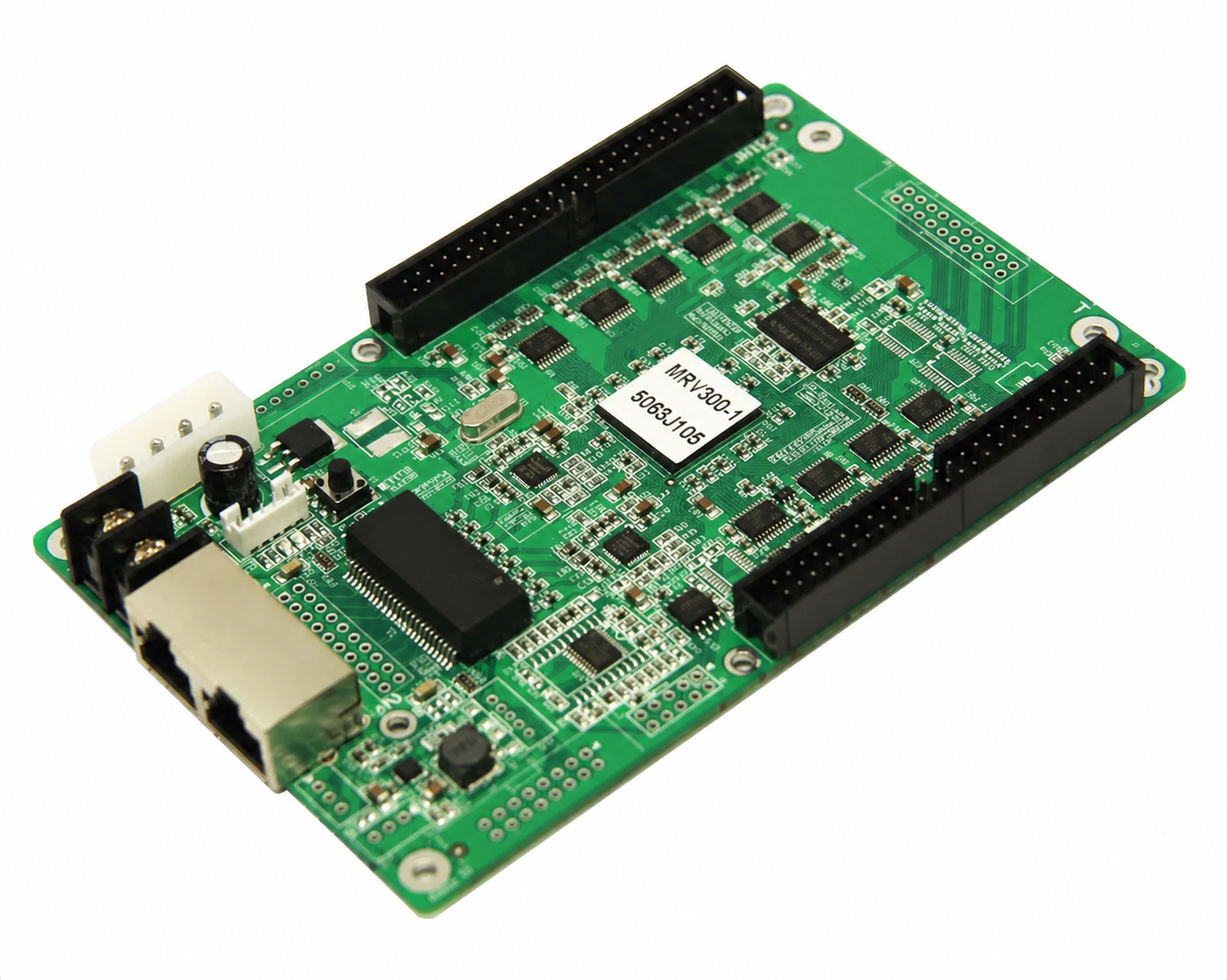
What is the NovaStar MRV300-3 receiving card?
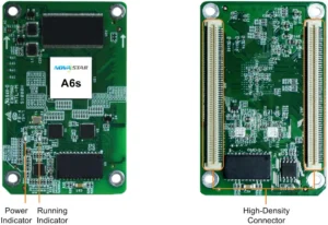
The NovaStar MRV300-3 is a legacy MRV300 receiving-card variant with female connectors on the top of the board. It is chosen to replace a card in a cabinet that presents matching male pins from its hub board or connection assembly. The connector gender is the first check: a card can share the same family name and still be unable to mate with the cabinet.
With the correct physical connection and cabinet file, the card sends data in one of the documented MRV300 arrangements: 16-group RGBR, 20-group RGB or 64-group serial. These are cabinet-output choices, not a reason to substitute a different suffix.
MRV300-3 key features
Top-side female interface for the existing mating pins
MRV300-3 has the same top-side placement as MRV300-1, but the connection is female instead of male. That small visual difference changes how the board attaches. Compare the socket and the pins together before purchasing a spare.
Original output modes for older cabinet wiring
RGBR parallel, RGB parallel and serial data layouts are supported by the MRV300 family. The existing hub board, module wiring and saved configuration decide which layout belongs in the cabinet. A generic capacity figure cannot identify it.
Information that helps a repair stay contained
Configuration readback, temperature, power-voltage and Ethernet-status checks help distinguish a configuration issue from a cable or power problem. The card can also use a pre-stored picture in a compatible cabinet, but that should be configured while the screen is working.
NovaStar MRV300-3 specifications
The connector row identifies the -3 model. The operating values below come from NovaStar’s MRV300 V2.1.1 specification.
| Model identity | Female connector on top |
|---|---|
| Parallel data modes | 16-group RGBR or 20-group RGB |
| Serial data mode | 64 groups |
| Maximum resolution | 256 × 226 pixels |
| Input voltage | 3.3 V minimum, 5.0 V typical, 5.5 V maximum |
| Input current | 0.33 A minimum, 0.50 A typical, 0.55 A maximum |
| Operating environment | −20°C to +70°C; 10% to 90% RH |
MRV300-3 or MRV300-1: same side, different connector
Both cards put their headers on the top side. MRV300-1 has exposed male pins; MRV300-3 has female sockets. A cabinet with male mating pins needs the -3 connection. A cabinet that expects the card’s exposed pins needs the -1 connection. Looking only at the side of the board misses the decision that controls physical fit.
Read the entire label on the old card, then photograph both the card and the cabinet interface before removing anything. If the card is unreadable, a clear photo of the mating hardware is more useful than a claim that the display is an “MRV300 system.” Send those photos through our MRV300-3 compatibility request for a specific next step.
MRV300-3 female-header and 50-pin mating-board fit
The MRV300-3 uses the family’s two 50-pin cabinet interface. It is not a direct-HUB75E card. Verify that the top-side sockets meet the cabinet’s pins cleanly, the board sits on the intended standoffs and the installed hub board still matches the original data arrangement.
| What to check | Reason before ordering | What to retain |
|---|---|---|
| Top-side female sockets meet male pins | Prevents a gender mismatch that cannot be corrected in software. | Card orientation and standoff position. |
| Cabinet record says RGBR or RGB | The two parallel data groupings are different. | The original output setting and cabinet file. |
| LED-bar layout is present | Serial line order controls the final picture. | The original bar sequence. |
MRV300-3 replacement and cabinet-file restore
Before taking out a working card, open NovaLCT and read back the cabinet configuration. That file stores the scan, module wiring and output arrangement for the cabinet. Firmware is different: it runs the card itself. Keep the configuration and card photos with the cabinet record.
Install one confirmed MRV300-3 and restore the file to that cabinet first. Check a known image for correct row order, colour and brightness before applying anything to the rest of the wall. A card that is detected on the network can still show a distorted picture when it receives a file from a different cabinet.
MRV300-3 vs MRV300-2 and MRV300-4
Each suffix is a physical connection description. Choose the exact label and mating format; none is a general upgrade.
MRV300-3 datasheet, firmware and NovaLCT
Use the datasheet to confirm the top-side female suffix. Save a working configuration before replacing a card. An exact public MRV300-3 firmware package is not available from the verified sources, so a generic firmware file is not a safe update choice.
NovaStar MRV300-3 FAQ
What does MRV300-3 mean?
It identifies the MRV300 hardware variant with female connectors on the top of the board.
Can MRV300-1 replace MRV300-3?
Not as a like-for-like spare. It has male rather than female top-side connectors.
What is the MRV300-3 maximum resolution?
The V2.1.1 specification lists 256 by 226 pixels. Also confirm the cabinet wiring and output mode.
Does MRV300-3 use direct HUB75E outputs?
No. It uses the MRV300 two-50-pin cabinet interface and needs a matching hub board.
What should I save before replacement?
Read and save the working configuration in NovaLCT, plus clear photos of the card and its mating connection.
Why should one cabinet be tested first?
A mismatched file can produce wrong row order or colour even when the card communicates normally.
Where can I find MRV300-3 firmware?
An exact public package is not available from the verified sources. Do not use a generic update on a working legacy cabinet.
What is needed for a compatibility check?
Send the card label, both board sides, cabinet mating hardware and saved configuration if available through our compatibility request form.
MRV300-3 replacement checks before the cabinet is opened
What a replacement can and cannot solve
An MRV300-3 replaces a failed card only when the cabinet has matching top-side male pins and the rest of the cabinet design is compatible. It cannot fix a damaged hub board, a loose module ribbon, missing power or a sender setup that was never saved. If several cabinets fail in a row or a new card is not detected, stop before changing more boards. Inspect the shared cable and hub connection first.
For a single-cabinet fault, work in a simple order. First compare the socket position and connector gender. Next install one card without changing firmware. Then load the saved cabinet file and test it with a known signal. Only after that should you investigate the module connection, signal cable or power path. This keeps every result meaningful: you know whether the repair changed the connector fit, the configuration or the displayed image.
If the card is being bought as a preventative spare, keep it with a cabinet photo and a copy of the configuration file. A future technician can then confirm why it was selected instead of treating an unlabelled MRV300 card as interchangeable.
Keep the repair evidence together
Female sockets are made to receive the matching pins. Do not press a male-header card into that connection, bend pins to make a different suffix fit or assume an adapter will preserve the original mapping. A poor mating connection can create an intermittent cabinet fault that looks like a network or module problem after the panel is closed again.
When the old card still works, record three things before the swap: the full label, photos of each connected edge and a NovaLCT readback of the cabinet configuration. When it has already failed, collect the hub-board marking, module part number, cabinet voltage and a photo of the mating pins. Those details give a support technician enough evidence to distinguish an MRV300-3 spare from a different MRV300 arrangement.
The goal is a controlled repair: one confirmed hardware match, one saved cabinet record and one test cabinet. It is faster and safer than buying several look-alike cards and discovering the connection or screen mapping is wrong after the wall has been taken apart.
Reviews
There are no reviews yet.