
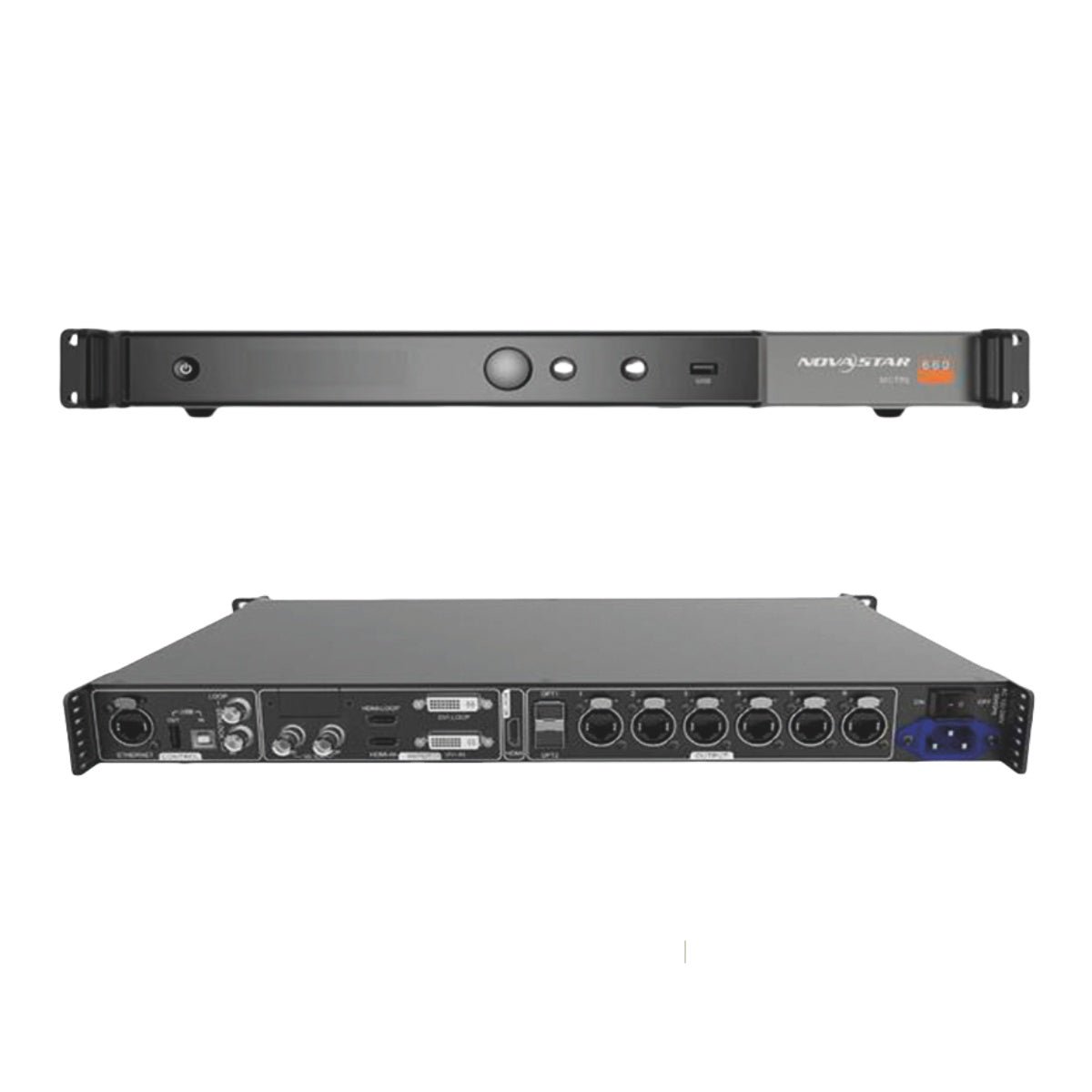
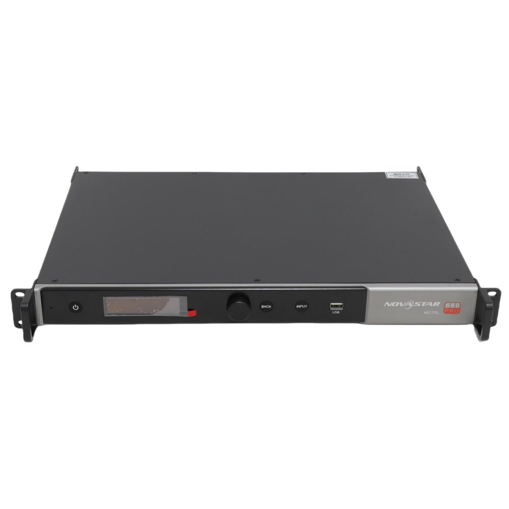
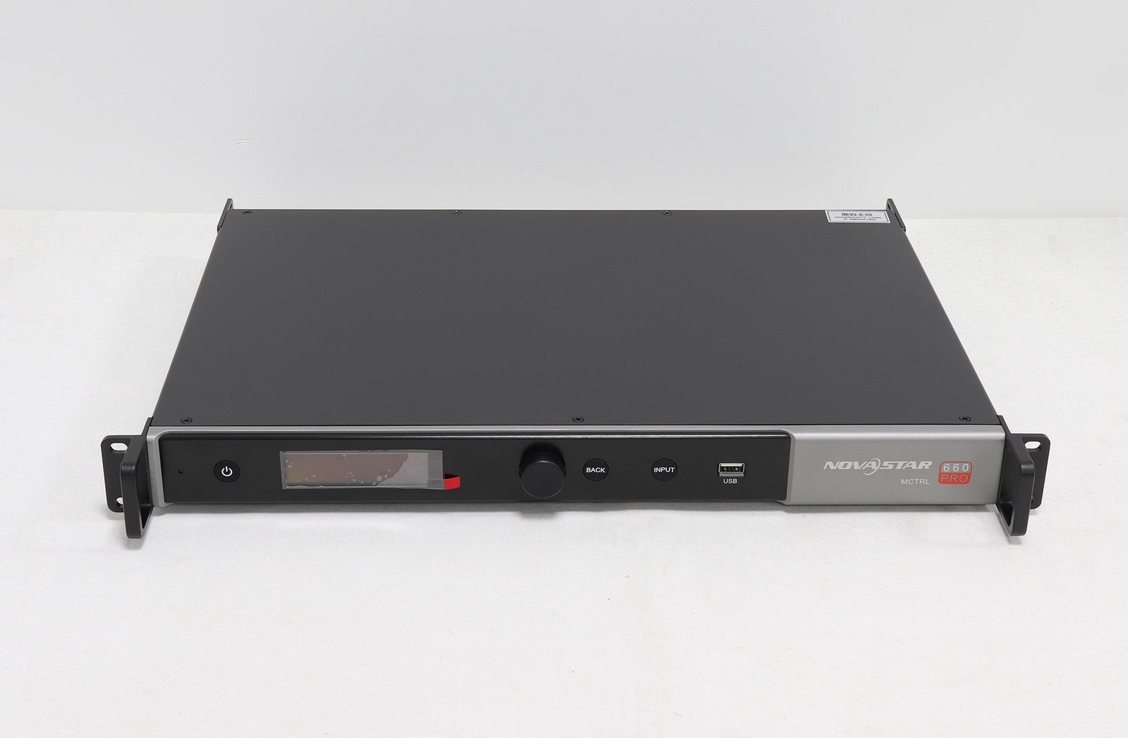
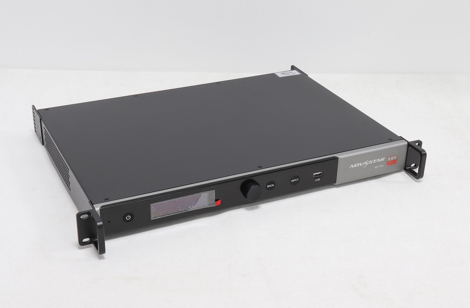
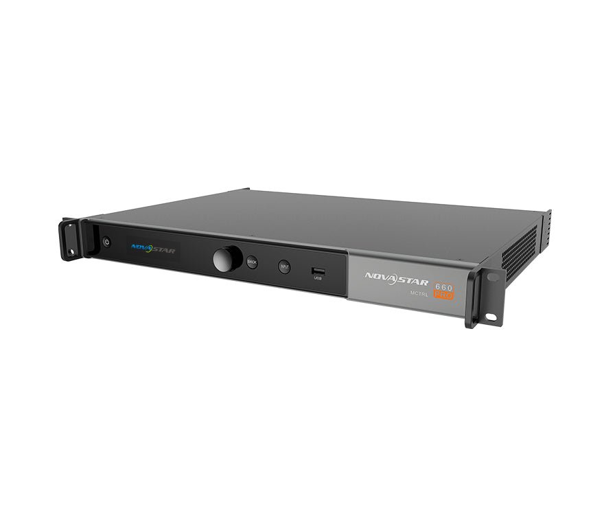
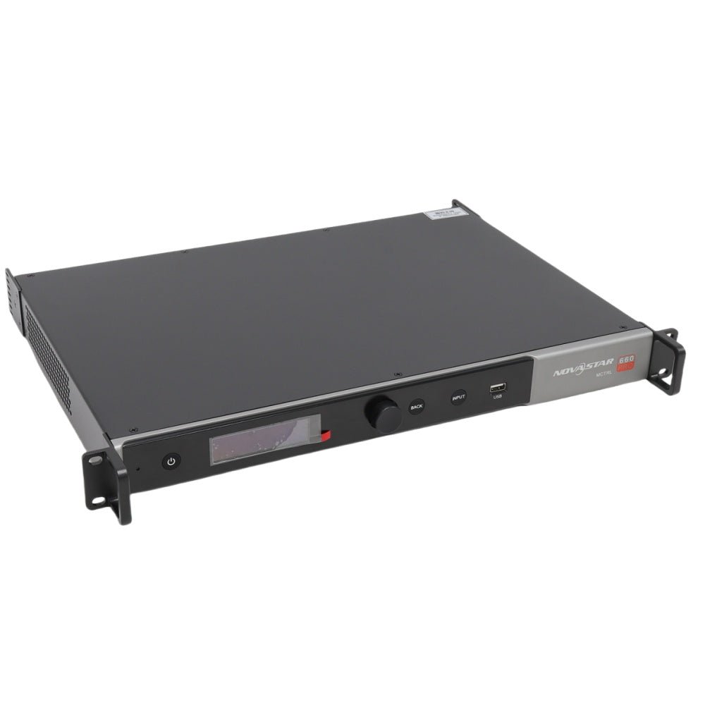
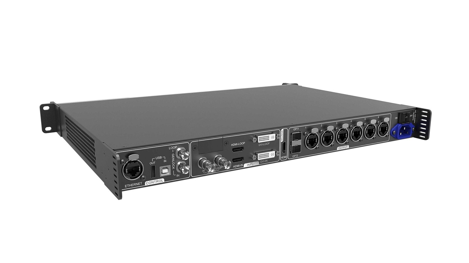
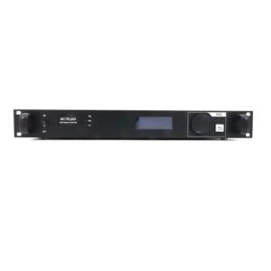
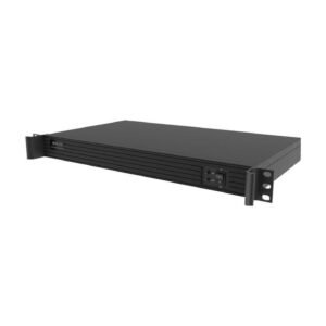
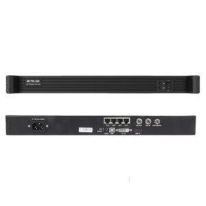
The NovaStar MCTRL660 Pro is an independent sending controller for professional LED displays that need 3G-SDI, Genlock, low-latency operation or long-distance 10G optical transmission. It accepts one HDMI 1.4a, single-link DVI or 3G-SDI source and sends the mapped image through six Gigabit Ethernet ports or a main-and-backup pair of optical ports.
It can also switch into fiber-converter mode, making it useful when the controller and LED wall are separated by a long cable run. The MCTRL660 Pro does not scale video, build multi-layer compositions or play content by itself, so the source or an upstream video processor must provide the required canvas.
What makes the MCTRL660 Pro different?
Broadcast and live production Connect a progressive 3G-SDI source up to 1920×1080@60Hz and loop it to another device. Genlock IN and LOOP help synchronize multiple controllers with a Bi-Level, Tri-Level or Black burst reference.
Low-latency camera workflows With low-latency mode and input-source sync enabled, and with cabinets connected vertically, NovaStar states that delay from the source to the receiving card can be reduced to one frame.
Fiber runs between control and display The controller's 10G optical interface can carry the same six-port LED data over duplex LC fiber. The official specification supports up to 10 km over OS1/OS2 single-mode fiber or 300 m over OM3/OM4 multimode fiber when the correct optical modules are used.
Rental and fixed installations Input monitoring, Ethernet-port redundancy, one-click backup and restore, front-panel controls and browser access give technicians several ways to commission and recover a system.
MCTRL660 Pro specifications
| Specification | MCTRL660 Pro |
|---|---|
| Video inputs | 1× 3G-SDI, 1× HDMI 1.4a, 1× single-link DVI |
| Input loop-through | 3G-SDI LOOP, HDMI LOOP, DVI LOOP |
| Maximum 8-bit input | 1920×1200@60Hz |
| 10/12-bit HDMI or DVI | Up to 1920×1080@60Hz |
| Custom input examples | Up to 3840×600@60Hz wide or 800×3840@30Hz tall |
| Ethernet outputs | 6× Gigabit RJ45 |
| Per-port capacity | 650,000 pixels at 8-bit; 325,000 at 10/12-bit |
| Optical interface | 2× 10G, with OPT1 main and OPT2 backup |
| Working modes | Sending card or fiber converter |
| Synchronization | Genlock IN/LOOP; Bi-Level, Tri-Level and Black burst |
| Control | Ethernet, USB IN/OUT, front-panel OLED and knob, web interface |
| Device cascade | Up to 8 units |
| Power | 100–240 VAC; 20 W rated |
| Dimensions | 482.6 × 356.0 × 50.1 mm |
| Weight | 4.6 kg |
Specifications are based on NovaStar's MCTRL660 Pro V1.4.1 documentation. Download the MCTRL660 Pro datasheet for the complete connector, environment and supported-resolution tables.
MCTRL660 Pro load capacity and supported resolutions
At 8-bit, the MCTRL660 Pro supports a total input canvas up to 1920×1200@60Hz, or 2,304,000 pixels. At 10-bit or 12-bit, HDMI and DVI input are limited to 1920×1080@60Hz, or 2,073,600 pixels.
Each Ethernet output can map up to 650,000 pixels at 8-bit or 325,000 pixels at 10/12-bit. Both limits matter: the complete wall must fit inside the controller's supported canvas, and the cabinets assigned to each port must stay below that port's limit.
For example, a 1920×1080 wall is within the 8-bit and 10/12-bit canvas limits. A 2560×960 source is supported at selected refresh rates, but it still needs a valid six-port cabinet map. A 3840×2160 4K60 source is not supported directly.
Before ordering, confirm the wall's total width and height in pixels, refresh rate, input bit depth, receiving-card model and the number of pixels assigned to each data port.
MCTRL660 Pro sending mode and Ethernet outputs
In sending mode, the MCTRL660 Pro maps one prepared video source across six Gigabit Ethernet outputs. Each port carries the cabinets assigned to it, while the complete canvas must remain within the controller's total loading limit.
The optical interface can carry the same mapped image as the six Ethernet outputs. It does not create a second independent canvas.
MCTRL660 Pro fiber converter mode and optical backup
OPT1 is the main optical input/output and corresponds to all six Gigabit Ethernet ports. OPT2 is its backup. This arrangement provides a protected six-port optical path rather than two independent groups of outputs.
In fiber-converter mode, the unit converts between optical and electrical LED data. When optical is the input, the six RJ45 ports become outputs. When the six RJ45 ports are inputs, the optical interface becomes the output. A long-distance system normally needs compatible equipment at the far end to convert the optical data back to the electrical connections used by the cabinets.
If you are planning a fiber link, verify the SFP module type, connector, wavelength, fiber grade and distance as a complete system. The controller specification calls for duplex LC fiber: 1310 nm single-mode or 850 nm multimode.
MCTRL660 Pro inputs, loop-through, Genlock and low latency
Use HDMI or DVI when you need custom resolution settings, 10/12-bit input, or image mirroring. Use 3G-SDI when the production chain comes from a compatible camera, switcher or router and must remain in an SDI workflow.
The SDI input supports progressive signals up to 1920×1080@60Hz. It does not support input-resolution or bit-depth settings, and the manual states that SDI does not support image mirroring. Interlaced SDI sources do not support the low-latency function.
The DVI, HDMI and SDI loop connectors pass the selected signal family onward for monitoring or distribution. They do not add scaling or create another LED output canvas.
To use the documented one-frame low-latency workflow, enable low latency and input-source synchronization, then follow NovaStar's vertical cabinet-connection requirement. If a fixed latency budget is critical, validate the complete camera-to-screen chain before the event.
MCTRL660 Pro setup and control options
For a simple, regular wall, the front-panel quick-configuration workflow is:
- Select the input source.
- Set the input resolution and refresh rate for HDMI or DVI.
- Set the input bit depth.
- Run quick screen configuration and confirm the cabinet map.
- Save the final settings and a known-good backup.
For full receiving-card configuration, cabinet mapping, brightness adjustment, monitoring and calibration, connect a computer by USB and use NovaLCT. NovaStar's manual specifies NovaLCT V5.2.0 or later. SmartLCT V3.2.0 or later supports visual cabinet layout, seam-brightness adjustment, monitoring and hot-backup workflows.
The MCTRL660 Pro also provides browser control. Connect its Ethernet control port directly to a computer or place both devices on the same LAN, find the controller's IP address, and open it in a browser. Browser control is convenient for routine settings, but it does not replace NovaLCT for loading RCFG files and several advanced system functions.
MCTRL660 Pro manual, datasheet, software and firmware
Firmware download: MCTRL660 Pro firmware package. Match it to the exact hardware version, save the working configuration and read the release notes before updating.
Direct PDF links: MCTRL660 Pro User Manual PDF · MCTRL660 Pro Datasheet PDF
MCTRL660 Pro applications and system fit
Choose the MCTRL660 Pro when the video source is already prepared at a supported resolution and the project needs one or more of its professional interfaces: 3G-SDI, Genlock, six Ethernet outputs, protected 10G optical transmission, low-latency operation, or fiber-converter mode. That combination fits touring LED walls, live events, sports venues, broadcast-adjacent systems, security monitoring and fixed installations with a remote control room.
Choose a different signal chain when the source needs to be scaled, cropped, switched seamlessly, layered or converted from 4K60. In that case, place a suitable video processor before the MCTRL660 Pro, or select an all-in-one NovaStar video processor that combines processing and LED sending.
MCTRL660 Pro vs MCTRL660, MCTRL R5 and MCTRL4K
| Buying need | Best starting point | Why |
|---|---|---|
| Basic HDMI/DVI wall without SDI, Genlock or optical output | MCTRL660 | Simpler and usually more economical; verify its four-port capacity against the project |
| 3G-SDI, Genlock, six ports or switchable fiber conversion | MCTRL660 Pro | These are the Pro model's defining workflow advantages |
| Higher loading capacity and rotation workflows | MCTRL R5 | Up to 3840×1080 and eight Ethernet outputs; designed for rotation-oriented applications |
| 4K-class input, HDR and much larger output capacity | MCTRL4K | Better fit when the source and wall exceed the 660 Pro's 1920×1200 class |
| Scaling, source switching and integrated processing | NovaStar video processors | An all-in-one processor is more appropriate than a sending-only controller |
The best choice depends on the source format as much as the pixel count. A smaller wall can still require the MCTRL660 Pro because of SDI or Genlock, while a larger HDMI wall may need the R5, MCTRL4K or an all-in-one processor.
MCTRL660 Pro frequently asked questions
How many pixels can the MCTRL660 Pro control?
Up to 1920×1200@60Hz at 8-bit, which is 2,304,000 pixels. For 10/12-bit HDMI or DVI, the maximum is 1920×1080@60Hz. Each Ethernet port also has its own limit: 650,000 pixels at 8-bit or 325,000 at 10/12-bit.
Can the MCTRL660 Pro accept a 4K input?
No. Its standard maximum is 1920×1200@60Hz, with specific custom wide or tall resolutions supported inside the documented timing limits. Use an upstream scaler to create a supported canvas, or choose an MCTRL4K-class controller when a 4K source is required.
Is the MCTRL660 Pro a video processor?
It is an independent LED sending controller. It maps a prepared video source to NovaStar receiving cards, but it is not an all-in-one scaler, multi-layer compositor or media player.
Can it work as a fiber converter?
Yes. In fiber-converter mode it converts between the 10G optical interface and six Gigabit Ethernet data paths. OPT1 is the main optical path and OPT2 is backup.
Are the two optical ports independent outputs?
No. Both correspond to the same six Ethernet ports. OPT1 is the main input/output and OPT2 backs it up.
What software is used to configure it?
NovaLCT V5.2.0 or later and SmartLCT V3.2.0 or later are specified in NovaStar's manual. A browser can handle many routine settings over Ethernet, but advanced receiving-card and system work still requires the desktop software.
Does it support low latency with 3G-SDI?
Progressive SDI can participate in the low-latency workflow, but interlaced SDI does not. Achieving the documented one-frame result also requires low latency and source sync to be enabled and cabinets to be connected vertically.
Will it work with any LED receiving card?
It is designed for a NovaStar synchronous control system. Confirm the receiving-card family, firmware, cabinet configuration file and required features before purchase; do not assume every third-party or newer COEX receiving card has the same compatibility.
Confirm the MCTRL660 Pro production and fiber path before ordering
Start with the production requirements that make this model relevant: the SDI/HDMI/DVI source format, Genlock reference, acceptable latency, and whether the unit will send LED data or work as a fiber converter. Add the fiber distance and module type, screen resolution, bit depth, receiving-card model and six-port cabinet map. We can then check the complete MCTRL660 Pro path and identify a better controller or upstream processor if one part does not fit.
Reviews
There are no reviews yet.