
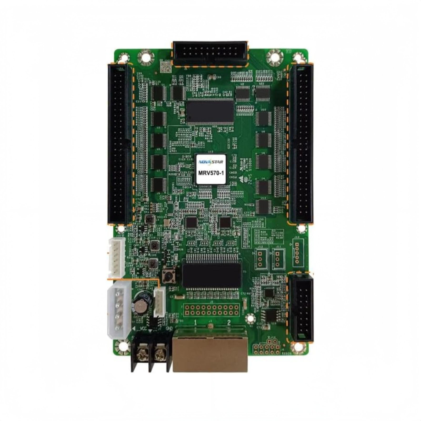
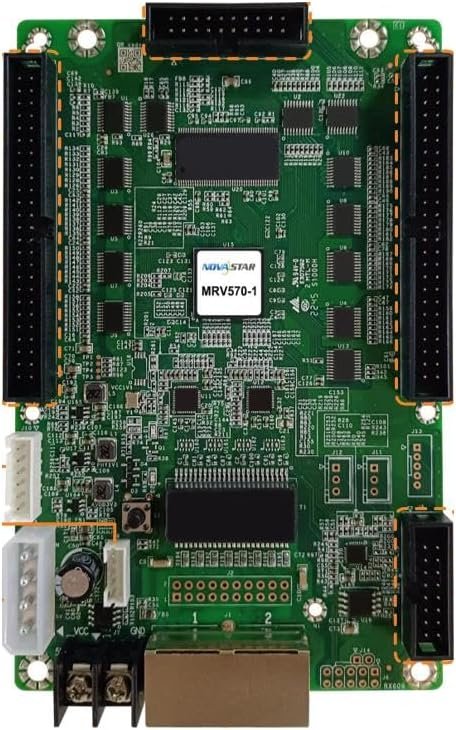
What is the NovaStar MRV570-1 receiving card?
The NovaStar MRV570-1 is the board inside a compatible LED cabinet that receives its mapped screen signal and sends the cabinet’s matching data to the LED modules. One card supports up to 512 × 256 pixels at 60 Hz. It suits an existing MRV570-1 cabinet or a new cabinet that has been designed and tested for this exact receiver.
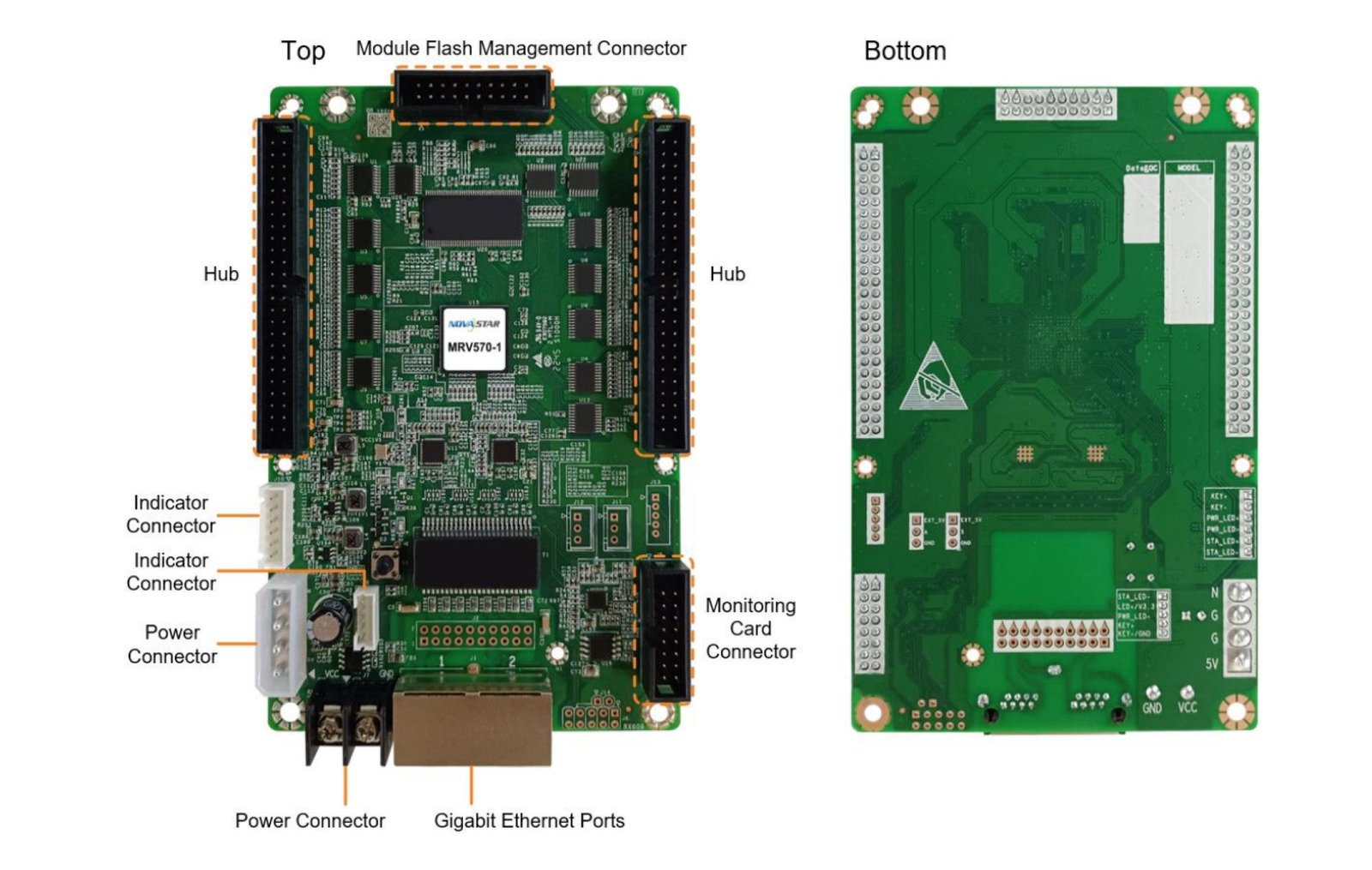
Its useful difference is not only capacity. MRV570-1 supports Module Flash management for calibration coefficients and module information. That matters when one cabinet has been repaired: the goal is not simply to make it light up, but to make it return looking like its neighboring cabinets. The board, hub arrangement, module type and saved cabinet settings still have to match before that recovery path can work.
MRV570-1 key features
- 512 × 256 at 60 Hz per receiving card: a useful ceiling for planning a compatible cabinet, not a number to divide among connectors or borrow for another card family.
- Module Flash management: stores calibration coefficients and module information so a correct recovery path exists when one newly fitted cabinet no longer matches the wall.
- 20 parallel RGB or 64 serial data groups: the cabinet’s hub board and modules decide which data path applies; the larger number is not an upgrade setting.
- Configuration readback and a stored image: preserve the working cabinet map before a swap, while the saved image can give a powered cabinet a visible state when its normal signal is absent.
- Monitoring support: with compatible cabinet hardware, temperature, voltage and Ethernet status can help point service work toward power, cabling or the receiver.
NovaStar MRV570-1 specifications
These official values help confirm a cabinet designed for MRV570-1. Read them together with the old-card label, hub/ribbon arrangement and saved configuration before ordering.
| Check | MRV570-1 value | Why it matters before ordering |
|---|---|---|
| Documented card-wide load | Up to 512 × 256 at 60 Hz | Use it as a total limit only after the final module map is known. It does not make a different cabinet or hub layout compatible. |
| Module data paths | Up to 20 parallel RGB groups or 64 serial groups | Match the original module and ribbon design. Serial mode assigns each of its 64 data cables to an LED strip. |
| Cabinet recovery features | Module Flash, configuration readback, stored image and calibration support | A matching receiver can be returned to a known-good cabinet configuration instead of being set up from a similar-looking wall. |
| Power and size | DC 3.8–5.5 V; 0.5 A; 2.5 W; 145.8 × 91.5 × 18.4 mm | Check the cabinet rail, footprint and clearance before treating a similar-size card as an alternative. |
| Compliance | RoHS; EMC Class B | Useful for component documentation; the completed display still needs the requirements for its own market and installation. |
Can one MRV570-1 run your LED cabinet?
Start with the pixels in one cabinet, not the pixels in the whole wall. A cabinet that is 512 × 256 or smaller may fit one MRV570-1 at 60 Hz, provided its module map and hub wiring are the approved arrangement. A wider, taller or irregular cabinet needs its actual module layout checked before anyone orders a single receiver.
The limit is shared by the complete card. Twenty parallel RGB groups or sixty-four serial groups describe how a compatible cabinet sends data to its modules; they are not separate blocks of 512 × 256 capacity. If a design uses folded ribbons, unusual scan wiring or LED strips, leave the final card count to the cabinet configuration rather than filling every number to a theoretical maximum.
MRV570-1 parallel and serial output modes
Most conventional cabinets use the documented parallel RGB path. A serial-data cabinet is different: MRV570-1 can carry 64 serial data cables, with each one able to drive an LED strip independently. That is useful for the module layout it was built for, especially when the rows or columns need their own path through the cabinet.
Neither mode should be chosen after the card is installed. The module driver, hub board and ribbon order already determine the correct signal map. Replacing the receiver without keeping that map can make the cabinet show swapped colors, scrambled rows or only part of the image. Photograph the ribbons and preserve the working configuration before taking the old board out.
MRV570-1 Module Flash and replacement recovery
A replacement can be electrically correct and still look wrong beside the rest of the wall. A slightly brighter cabinet, rough-looking white fields or a visible color shift often points to configuration or calibration information rather than a bad new board. MRV570-1 supports Module Flash management for calibration coefficients and module information, giving a compatible cabinet a way to retain the data behind its intended appearance.
Before a planned replacement, use NovaLCT to save the receiving-card configuration from the working cabinet. Keep it with the cabinet location and the photos of the original ribbons. After fitting the like-for-like card, restore and inspect one cabinet first. If it differs from its neighbors, check the saved map and valid calibration data before sending any file across the entire wall.
Module Flash is not a magic reset. It cannot make unrelated module batches, a wrong receiver model or an unknown configuration look identical. It simply preserves a recovery path when the cabinet hardware and its records genuinely match.
MRV570-1 stored image and monitoring support
The stored image has a practical role during service. At startup or when the normal video path is unavailable, it can keep a cabinet from looking like a dead black rectangle. That helps distinguish a signal-path issue from a cabinet that has no power, but it cannot fix a disconnected module ribbon or a bad pixel map.
The card also supports a connection to a monitoring card. In a cabinet fitted with the compatible monitoring hardware, temperature, supply voltage and Ethernet communication status can give the technician a useful place to start: inspect power first, the cable path next, then the receiver and modules. The receiving card alone is not a complete monitoring system, so the supporting cabinet hardware must be present.
MRV570-1 vs MRV560-1 and MRV532
Choose MRV570-1 when the cabinet is built for this 512 × 256 receiver and its Module Flash recovery path. MRV560-1 is a different legacy family with a 256 × 226 card-wide limit and top-side male/50P-specific fit. It is not a drop-in substitute simply because both cards can support serial data and service features.
MRV532 is a newer, denser ten-HUB320F card with capacity that changes by driver type and video bit depth. It can be the better choice for a newly engineered cabinet, but it is not an upgrade board for an existing MRV570-1 cabinet unless the cabinet maker has approved the hub, module, file and mounting conversion. For a repair, the original card label remains the safest first answer.
MRV570-1 datasheet, firmware and NovaLCT
The MRV570-1 datasheet page and direct MRV570-1 Datasheet PDF confirm capacity, power, dimensions, output modes and service features. Use them to confirm a real cabinet, not as a reason to substitute a different receiving-card family.
NovaLCT restores the cabinet’s configuration; firmware is separate and has to match the card PCB and module driver. No exact MRV570-1 firmware package has been independently verified for this store, so no guessed ZIP is offered. Preserve a working program and verify an exact package through the NovaStar download center before updating a screen that already works.
NovaStar MRV570-1 FAQ
What does the MRV570-1 do?
It is the receiving card inside a compatible LED cabinet. It receives the mapped screen signal and sends the cabinet’s matching data to the LED modules.
What is the MRV570-1 maximum resolution?
The official V1.0.0 document lists up to 512 × 256 at 60 Hz for one receiving card. The approved cabinet map and module design still decide whether it fits.
Can I divide the MRV570-1 capacity across its output groups?
No. The capacity is a card-wide ceiling. The 20 parallel RGB or 64 serial groups describe the matching module data path in the cabinet.
What does Module Flash do on MRV570-1?
It supports storage of calibration coefficients and module information. With matching hardware and valid records, that can help a repaired cabinet return to the wall’s intended appearance.
What should I save before replacing MRV570-1?
Use NovaLCT to save the working receiving-card configuration, record the cabinet location and photograph the module ribbon order. Restore and inspect one cabinet before changing the rest of the wall.
Can a stored image repair a scrambled cabinet?
No. It can show a saved image during startup or a missing normal source, but it cannot correct a wrong map, bad ribbon connection or failed module.
Does MRV570-1 provide full monitoring by itself?
No. It supports a monitoring-card connection and the relevant card status features. The cabinet needs the compatible monitoring hardware for that system to be available.
Can MRV570-1 replace MRV560-1 or MRV532?
Do not assume so. They have different capacity, hub/interface and approved cabinet-file paths. Use the installed card label unless a full cabinet conversion has been approved.
Should I update firmware during a normal repair?
Not automatically. Keep the known-good program and update only after an exact package is verified for the receiver PCB and module driver.
Reviews
There are no reviews yet.