
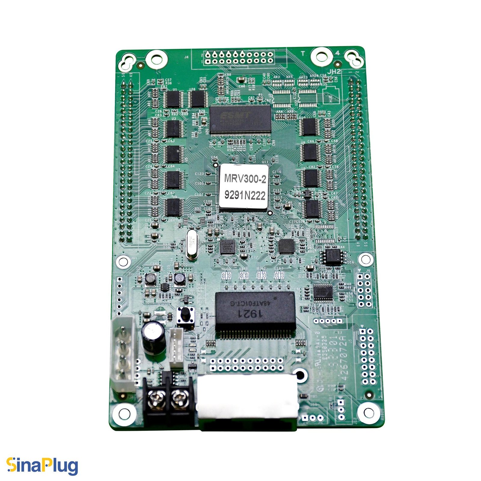
What is the NovaStar MRV300-2 receiving card?
The NovaStar MRV300-2 is an older MRV300 receiving-card variant made for cabinets whose two male data headers must sit on the bottom side of the board. It is a physical replacement choice. The lower header position can determine whether the card clears the cabinet frame, meets the hub board and lets the existing ribbon route reach without strain.
Once installed in the correct cabinet, MRV300-2 sends the configured display data through the MRV300 two-50-pin interface. It supports 16-group RGBR, 20-group RGB or 64-group serial output. Those operating modes are shared family facts; they do not make a top-side card and a bottom-side card interchangeable.
MRV300-2 key features
Bottom-side male connection for a specific cabinet layout
NovaStar identifies MRV300-2 as the male-connector-on-bottom model. That is the main reason to order it. Confirm the side from the component view and the way the cabinet’s hub board or ribbon socket meets the card before comparing any general specifications.
Data modes that keep an older cabinet wired as designed
The card can provide RGBR parallel, RGB parallel or serial data in the documented MRV300 arrangements. The right setting follows the installed modules and hub board. A replacement that is physically correct but uses the wrong stored configuration can light up with misplaced rows, wrong colours or missing areas.
Helpful service information without turning the repair into guesswork
Configuration readback, temperature, supply-voltage and Ethernet-status monitoring can help locate the cause of a cabinet fault. A pre-stored picture can be used in a compatible setup when the normal signal is absent. These are useful checks, but the first repair step remains preserving the working cabinet record.
NovaStar MRV300-2 specifications
The bottom-side connector is the model-specific detail below. The remaining values are the verified MRV300 V2.1.1 operating facts.
| Model identity | Male connector on bottom |
|---|---|
| Parallel output modes | 16-group RGBR or 20-group RGB |
| Serial output mode | 64 groups |
| Maximum resolution | 256 × 226 pixels |
| Input voltage | 3.3 V minimum, 5.0 V typical, 5.5 V maximum |
| Input current | 0.33 A minimum, 0.50 A typical, 0.55 A maximum |
| Operating environment | −20°C to +70°C; 10% to 90% RH |
| Thickness | About 1.6 mm board; about 18.5 mm overall |
How to identify the MRV300-2 bottom-side male connector
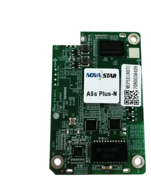
Read the label first: it should say MRV300-2. Then inspect the board in the same direction as the removed card. The long male header rows belong on the underside, not the top. A front-only listing photo can hide this difference, so check a photo that shows both the label and connector side before placing a multi-card order.
Also look for a cabinet clearance problem: standoffs, the frame, a power lead or a short ribbon can make a top-side male version unusable even if it shares capacity and power figures. If the original card cannot be read, send front-and-back photos plus a hub-board photo through our MRV300-2 compatibility request.
MRV300-2 cabinet clearance and 50-pin hub-board fit
The MRV300-2 does not replace a direct-HUB75E card. Its two 50-pin connection points meet a matching cabinet interface, and the bottom-side header location changes the physical path inside the cabinet. Check the hub board, socket direction and cable bend before ordering.
| Cabinet check | Why it belongs in the order decision | What to keep from the working cabinet |
|---|---|---|
| Bottom-side male headers reach the mating socket | Prevents a mechanical mismatch or blocked ribbon route. | The original board orientation and standoff clearance. |
| Hub or module record identifies RGBR | The parallel data grouping differs from RGB. | The 16-group RGBR configuration. |
| Hub or module record identifies RGB | A similar cabinet may use a different mapping. | The 20-group RGB configuration. |
| The display uses an LED-bar layout | Serial-data order is part of the final image. | The 64-group serial configuration and bar sequence. |
MRV300-2 replacement and NovaLCT configuration restore
With a working card still installed, use NovaLCT to read back and save the cabinet configuration. The file stores the scan, module wiring and output arrangement. Firmware is different: it runs the card, while the cabinet file describes the actual LED cabinet. Keep both the file and clear connection photos with the service record.
Fit one confirmed MRV300-2, restore that saved configuration to one cabinet and use a known signal to inspect image order, brightness and colour. Only then continue across the wall. This staged check is faster than pushing an uncertain configuration to several cabinets and then trying to identify which physical or mapping change caused the fault.
MRV300-2 vs MRV300-1, MRV300-3 and MRV300-4
The suffixes describe the connection hardware. Choose from the cabinet’s actual mating arrangement; a higher suffix is not a newer or better version.
| Model | Connector description | Physical decision |
|---|---|---|
| MRV300-1 | Male connector on top | Use only when the cabinet mating point is above the board. |
| MRV300-2 | Male connector on bottom | Use when the original male headers meet the cabinet from below. |
| MRV300-3 | Female connector on top | Different connector gender, even though the side is top. |
| MRV300-4 | Female connector on bottom | Same side as -2 but a different mating format. |
MRV300-2 datasheet, firmware and NovaLCT
Use the datasheet to verify the bottom-side male suffix and shared legacy facts. Preserve a working cabinet configuration before replacing the card. An exact public MRV300-2 firmware package is not available from the verified sources, so do not use a generic file as an upgrade.
NovaStar MRV300-2 FAQ
What makes MRV300-2 different from MRV300-1?
MRV300-2 has male connectors on the bottom. MRV300-1 has male connectors on the top. Match the cabinet mating side, not only the MRV300 family name.
What is the MRV300-2 maximum resolution?
The MRV300 V2.1.1 specification lists 256 by 226 pixels. Confirm cabinet wiring and output mode as well as pixel capacity.
Can I use MRV300-1 in a bottom-side MRV300-2 cabinet?
Not as a direct spare. Its header side differs, which can prevent it from fitting the hub board, cabinet clearance or ribbon route.
Does MRV300-2 use direct HUB75E outputs?
No. It uses the MRV300 family two-50-pin cabinet interface. Check the hub board and original wiring before ordering.
What should I save before an MRV300-2 replacement?
Read back the working cabinet configuration in NovaLCT and save it with the card and connection photos. The file contains the cabinet’s scan and wiring information.
Why should I test one cabinet first?
A wrong configuration can produce shifted rows or incorrect colours even when the replacement card is detected. Testing one cabinet keeps the diagnosis contained.
Can MRV300-2 show a stored picture?
It supports a pre-stored picture in a compatible cabinet. Configure it while the display works; it is not a substitute for the correct source and cabinet file.
Where can I get MRV300-2 firmware?
An exact public MRV300-2 firmware package is not available from the verified sources. Do not change a known-good legacy installation without an exact hardware match.
What photos help confirm MRV300-2 compatibility?
Send the printed card label, both sides of the board, the cabinet hub board, ribbon direction and required quantity through our compatibility request form.
Reviews
There are no reviews yet.