
What is the NovaStar VX2000 Pro all-in-one LED controller?
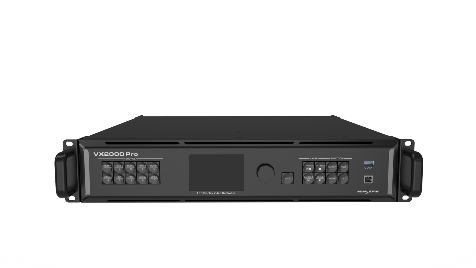
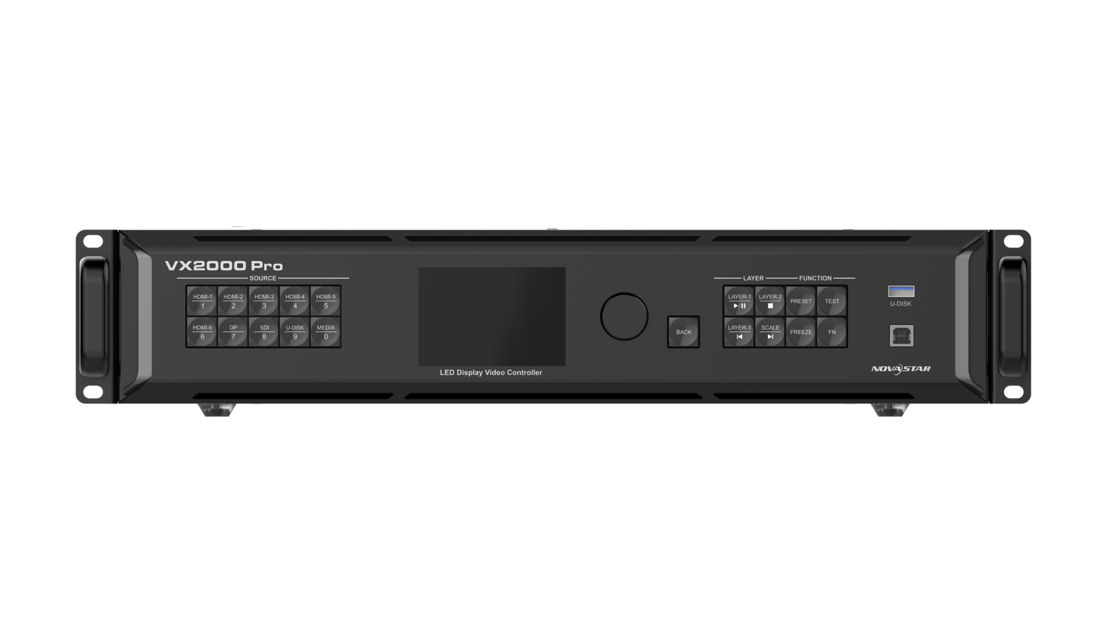
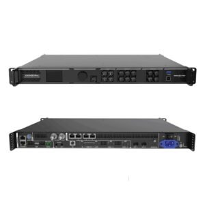
The VX2000 Pro combines video processing and LED sending in one 2U controller. It takes the show sources, builds the finished screen picture, and sends LED data to the receiving cards through twenty Ethernet outputs or planned fiber paths.
It is intended for a larger screen or a more demanding show than a compact all-in-one controller can handle. The two questions to answer first are whether the LED wall fits its 13-million-pixel output capacity and whether the source list fits its 4K input set.
VX2000 Pro key features
- Large 4K production inputs: accept HDMI 2.0, DisplayPort and 12G-SDI sources when a camera or media-server rack needs a current 4K60 path.
- Twelve shared layer resources: build a main image with supporting cameras, playback and graphics after calculating how much of the layer budget each large layer uses.
- Twenty LED ports: map a wide stage wall or multiple physical sections without pretending that total pixels are the only loading check.
- Fiber, Genlock and backup planning: make the long-run and timing design part of the system plan before the rack is installed.
VX2000 Pro specifications
| LED load and outputs | Up to 13 million pixels through 20 Gigabit Ethernet outputs. |
|---|---|
| 4K60 inputs | DP 1.2, 2× HDMI 2.0 and 12G-SDI up to 4096×2160@60Hz. |
| Layer resources | 12 shared 2K×1K resources with scaling, crop and presets. |
| Signal planning | Four 10G optical output paths, Genlock and configured backup options. |
Can the VX2000 Pro handle your 4K sources and LED wall?
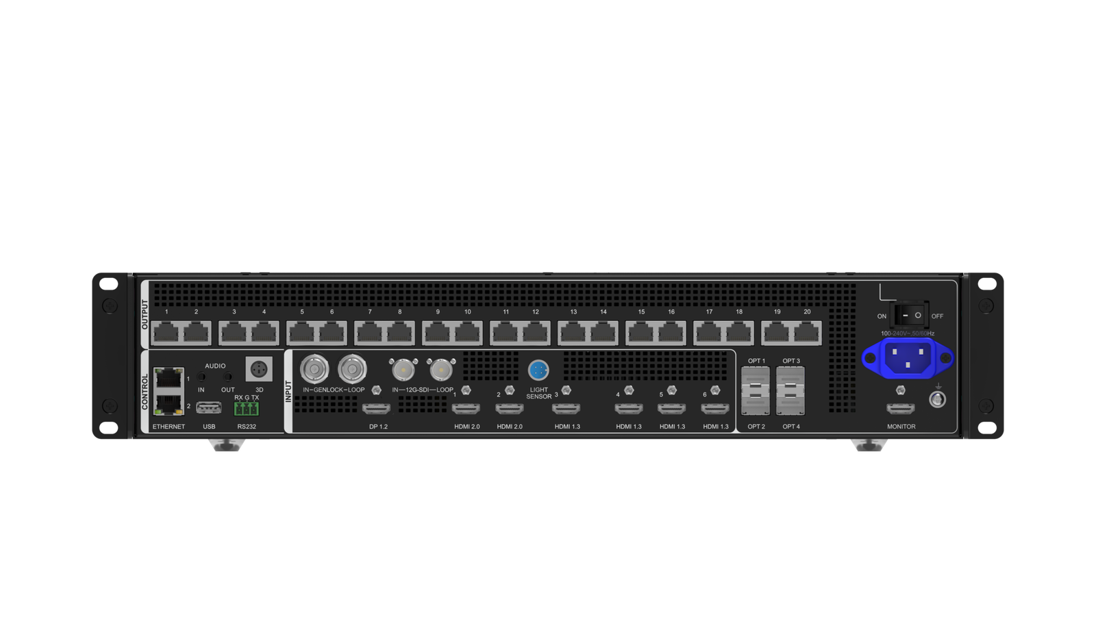
The controller accepts one DP 1.2, two HDMI 2.0, four HDMI 1.3 and one 12G-SDI input. DP, HDMI 2.0 and 12G-SDI can accept 4096×2160@60Hz within their documented formats. That gives a production rack room for a 4K graphics system, camera path and supporting 1080p feeds without adding a separate sending controller.
On the LED side, it loads up to 13 million pixels, with a maximum width of 16,384 pixels and height of 8,192 pixels. Twenty outputs give more routing room, but the total canvas and the physical cabinet load on each port must both fit. A wide wall that stays under 13 million pixels can still need a different map if one output bank becomes overloaded.
VX2000 Pro layer resources for a live LED show
The VX2000 Pro has twelve shared 2K×1K layer resources. They are a budget, not twelve identical full-size 4K windows: a 4K×2K layer uses four resources, a 4K×1K layer uses two, and a 2K×1K layer uses one.
For example, a large main camera or presentation layer can sit behind smaller playback, speaker and logo layers if the resource total fits. Plan that layout before the rack is built. A page that only says “12 layers” does not tell an operator whether the actual main image and overlays will fit at their intended size.
VX2000 Pro fiber paths, Genlock and backup planning
The twenty Ethernet ports are divided into two ten-port output banks. OPT 1 carries the output for Ethernet ports 1–10 and OPT 2 carries ports 11–20. OPT 3 and OPT 4 can copy or back up those respective banks. This makes the fiber plan readable: decide which wall area belongs to each bank, then decide which copy or backup path will be tested.
Genlock is useful when the LED image must share a timing reference with other controllers or production equipment. It is not a picture-quality setting for a single ordinary display. Use it when the full system needs timing alignment, and test it with the actual source and receiving-card chain.
When VX2000 Pro Bypass mode helps—and what it turns off
| Mode | Use it when | What the operator should expect |
|---|---|---|
| Video Controller | The source needs scaling, crop, layers or presets. | The controller processes the image before sending it to the wall. |
| Bypass | The source is already prepared and the shortest documented path matters. | Normal video processing is unavailable; do not expect a processed multi-layer layout in this mode. |
| Fiber Converter | The system needs to transport LED data over the planned fiber path. | Use the documented output-bank and backup design rather than treating fiber as an unplanned adapter. |
Latency is mode dependent. The specification documents zero-frame behavior in Bypass and Fiber Converter modes, while Video Controller mode has a different latency range. Test the finished show path rather than making a blanket zero-latency claim.
VX2000 Pro setup with Unico, NovaLCT and VICP
Set up the LED wall before you build the show layout. Use NovaLCT for cabinet and receiving-card configuration, including the physical port map. Use Unico for controller operation and project management; the front panel and VICP can support on-site control.
- Confirm the correct cabinet and receiving-card data.
- Map the actual Ethernet order and output banks.
- Confirm the source formats and EDID where needed.
- Build layers, save a known-good preset and preview it.
- Test the input, device and output backup paths before the event.
- Back up the working configuration before any firmware change.
VX2000 Pro applications for large rental, broadcast and fine-pitch LED systems
These examples show where the controller’s inputs, layer budget and output-bank design solve a real operating problem. They do not replace a capacity and receiving-card check.
Large rental stages
Run a main presentation or camera image with supporting playback and logo layers, then recall a tested preset at each cue.
12G-SDI production feeds
Bring a documented 4K camera or switcher path into the controller when the source format and cable plan have been confirmed.
Ultra-wide LED walls
Use the 16,384-pixel maximum width and twenty ports for a wide canvas only after total and per-port load planning.
Protected signal paths
Plan primary and backup output banks, then test the actual source, device and data-link backup behavior before the show.
VX2000 Pro manual, datasheet, firmware and software
Keep the model-specific documents and configuration tools with the screen record. The manual explains procedures; use the source, screen and backup plan to decide when those procedures matter. Before an update, save the working screen configuration and read the release notes for the exact package.
VX2000 Pro user manual
Open the VX2000 Pro user manual page for setup and maintenance, or use the official VX Pro Series User Manual PDF.
VX2000 Pro datasheet
Use the VX2000 Pro datasheet page or the official VX2000 Pro Specifications PDF for connector and capacity details.
VX2000 Pro firmware
Use the verified VX2000 Pro Firmware V1.3.1 ZIP with its release notes. Save the current configuration first.
VX2000 Pro vs VX1000 Pro: when do you need the larger controller?
| Model | LED capacity | Ethernet outputs | Layer resources | Choose it when |
|---|---|---|---|---|
| VX1000 Pro | 6.5M pixels | 10 | 6 × 2K×1K | The wall and live layout fit a ten-port, 6.5M-pixel plan. |
| VX2000 Pro | 13M pixels | 20 | 12 × 2K×1K | The wall needs more output capacity, more layer resources, a wider canvas or the larger input set. |
The decision is not simply “bigger is better.” Choose the VX2000 Pro when the actual port plan, source list and live layout need the step up. A smaller controller is easier to plan and operate when it already fits the system.
VX2000 Pro FAQs for inputs, layers and backup
Does twelve layer resources mean twelve full 4K layers?
No. A 4K×2K layer uses four 2K×1K resources, a 4K×1K layer uses two, and a 2K×1K layer uses one.
Can Bypass run the normal scaled and layered show image?
No. The specification states that normal video processing is unavailable in Bypass mode. Use Video Controller mode when scaling and layers are needed.
Which optical ports are the primary outputs?
OPT 1 and OPT 2 carry the two ten-port Ethernet output banks. OPT 3 and OPT 4 copy or back up those corresponding banks.
Does 3D affect output capacity?
Yes. With a Side-by-Side or Top-and-Bottom source, enabling the documented 3D function halves the output capacity.
Reviews
There are no reviews yet.