
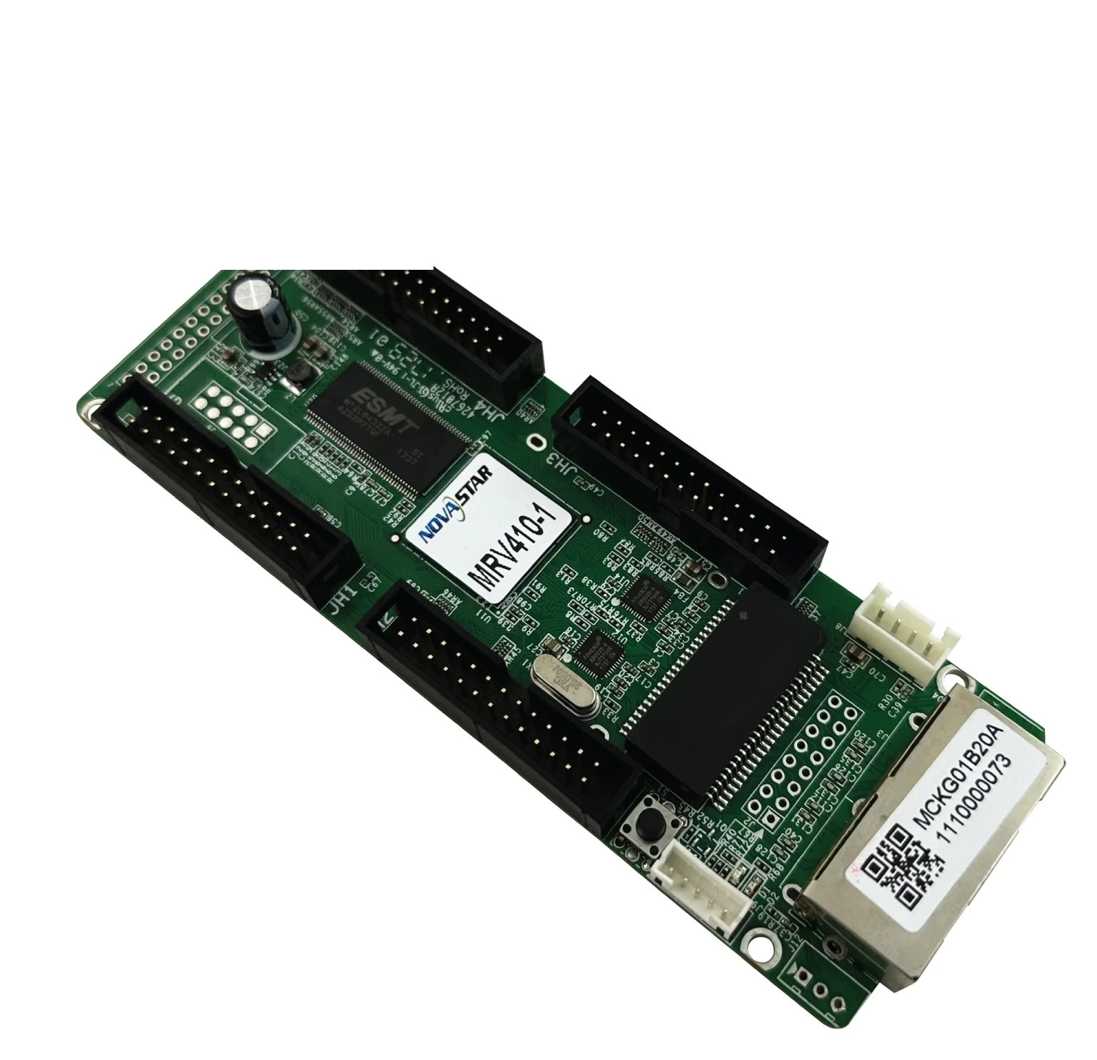
What is the NovaStar MRV410 receiving card?
The NovaStar MRV410 is a receiving card for an existing LED cabinet. It takes the image data sent through the cabinet, then passes the right row, column and clock signals to the modules through the cabinet’s matching board and ribbons. It is usually bought when a wall already uses an MRV410, or when the original parts list specifically calls for its CE-EMC Class B documentation.
NovaStar describes the MRV410 as the EMC version of the older MRV210. That relationship is useful for identifying the card family, but it is not permission to substitute one card for the other. A successful replacement still depends on the printed model, connector direction, hub board, module wiring and saved cabinet settings. Get one of those wrong and a new card can leave a cabinet black, mirrored or scrambled even though the rest of the wall is working.
MRV410 key features
- 256 × 226 pixels across one card: use that ceiling to decide whether one MRV410 can cover a cabinet. It is the card-wide budget, not a separate allowance for each output.
- Four 26-pin output interfaces: the card can work in several documented data modes, but the cabinet’s hub board and module wiring decide which mode belongs in that cabinet.
- Configuration readback: NovaLCT can preserve a working card’s settings before removal, which gives the replacement a known cabinet map instead of a guess.
- Temperature, supply-voltage and Ethernet-status checks: these readings help separate a card fault from a loose network lead or a cabinet power problem before parts are changed.
- Pixel calibration support: when the cabinet has the matching calibration data, it can help a repaired cabinet sit closer to its neighbors instead of looking brighter, darker or a different color.
NovaStar MRV410 specifications
These are the values that change cabinet fit and site conditions. Confirm the module driver, scan and wiring with the cabinet maker before treating the maximum load as an order quantity.
| Check | MRV410 documented value | Why it changes an order |
|---|---|---|
| Product type | LED receiving card | It belongs inside an LED cabinet; it is not a video processor or a standalone source switcher. |
| Maximum load | 256 × 226 pixels per card | Use the total canvas, not the number of outputs, to decide whether a cabinet needs another card. |
| Output interfaces | Four 26-pin interfaces | The hub board and ribbon order must match the original cabinet design. |
| Data modes | 16 RGBR, 20 RGB, 24 RGB parallel; 64 serial | The module and scan design choose the mode; more listed modes do not make a different cabinet compatible. |
| Power input | DC 3.3–5.5 V, 0.33–0.55 A | Check the cabinet rail before connection, especially on older walls with mixed replacement parts. |
| Operating range | -20 to +70 °C; 10–90% RH | A hot, damp enclosure needs an installation review; the card rating is not a cure for water or airflow problems. |
| EMC document | EU CE-EMC Class B | Useful when the original part or procurement file calls for that documented class. |
MRV410 load capacity and four-output planning
The MRV410’s published limit is 256 × 226 pixels for the complete card. The four 26-pin interfaces share that one limit. They do not create four separate 256 × 226 blocks, so multiplying the number by four produces a cabinet plan that can fail before the screen is mapped.
Start with the finished cabinet canvas. A 128 × 226 cabinet is 28,928 pixels; a 256 × 226 cabinet reaches the published ceiling. If the module layout, scan arrangement or pixel map needs more than that, split the cabinet across the number of receiving cards the cabinet design specifies. Do that calculation before ordering spares, not after a card has already been installed.
The 16, 20 and 24 parallel data-group options describe how the MRV410 can connect to different module designs. They are not a performance ladder. Your modules, decoder signals and hub board determine the correct mode. A card that powers up with a mismatched ribbon layout may show repeated rows, a shifted image or color blocks; it has not become the wrong card because the features are missing, but because the cabinet map and connection path are wrong.
MRV410 CE-EMC Class B and project compliance
Choose the MRV410 when the existing cabinet uses it or when a parts list asks for an MRV410 with CE-EMC Class B documentation. That is a real distinction from a generic “compatible” card: it gives the buyer the same receiving-card document that was specified for the wall.
Class B in the card specification does not certify every completed LED wall. The cabinet metalwork, power supplies, module wiring, grounding, controller and final installation also affect the finished system. If a project needs formal compliance evidence, keep the MRV410 document with the purchase record and have the responsible project team confirm the complete cabinet and installation requirement. It is a procurement check, not a slogan.
MRV410, MRV410-1, MRV410-2, MRV410-3 and MRV410-4 cabinet fit
The suffix on the label matters. NovaStar lists MRV410-1 with a male connector on top, MRV410-2 with a male connector on the bottom, MRV410-3 with a female connector on top and MRV410-4 with a female connector on the bottom. That detail decides whether the mating connector, hub board, ribbon path and cabinet clearance line up.
Before ordering, photograph the full label and both sides of the failed card. Then compare the male or female connection and its position with the cabinet’s mating part. Do not order a different suffix because the board outline looks similar. A connector that faces the wrong way can force a ribbon bend, miss the cabinet pins or prevent the door from closing.
Confirm the hub board and module wiring at the same time. The MRV410’s four 26-pin interfaces are only part of the connection. The cabinet may use a board between the receiving card and modules, and that board determines the actual ribbon order and power path.
MRV410 replacement and NovaLCT configuration
If the old card can still communicate, read it in NovaLCT before removing it. Save the receiving-card program and the cabinet configuration file, label the files with the cabinet location, and take photos of the card label and ribbon positions. Those three records let you restore the cabinet that already worked.
The program tells the receiving card how to work with the module driver and decoding signals. The cabinet configuration file holds the scan, wiring and pixel arrangement for that physical cabinet. They are related, but one cannot replace the other. A newly installed card with a correct program but the wrong cabinet map can still display a mirrored or scrambled picture.
Install one card, restore the files and test one cabinet before copying anything across the wall. Check that the cabinet joins the image at the right position, that colors are in the right order, and that its brightness matches the cabinets on either side. If it remains dark, inspect the power rail and Ethernet path before sending settings to every card. The MRV410 can report supply voltage and Ethernet communication status, which can help narrow the fault instead of swapping good parts.
For a dead card with no readable configuration, use the saved file from the same cabinet position or obtain the exact cabinet file from the display maker. A file from a different screen that merely uses MRV410 hardware is not a safe substitute.
MRV410 vs MRV210 for a replacement
MRV410 is documented by NovaStar as the EMC version of MRV210, so the two names often appear together in reseller listings. For a working wall, choose the model printed on the old card or the model named in the cabinet’s original documentation. The relationship explains why the cards are discussed together; it does not prove that their connector orientation, configuration or project documentation can be interchanged.
If the original card says MRV410, order the matching MRV410 suffix after checking its connector position. If the cabinet record calls for an MRV210 or a different card, keep that original model unless the cabinet maker has approved a tested change. For a new cabinet design, use the module maker’s approved receiving-card list; an older legacy card is not a general upgrade.
MRV410 datasheet, firmware and NovaLCT
Use the MRV410 datasheet page when you need the full pin assignment, output-mode definitions, electrical limits or the MRV410 suffix list. The MRV410 Datasheet PDF is the direct official specification file.
Use NovaLCT to read a working card, save the cabinet configuration and restore a verified replacement. Firmware is different: it must match the board and module-driver combination. No current exact MRV410 firmware ZIP is presented here, because a plausible-looking package is not safer than the known-good program already running in a wall. Check the NovaStar download center for a verified package before changing a working system.
NovaStar MRV410 FAQ
What does the NovaStar MRV410 do?
The MRV410 sits in an LED cabinet. It receives the mapped screen data from the controller or previous cabinet and sends the correct signals to that cabinet’s LED modules.
Is 256 × 226 the limit for each MRV410 output?
No. NovaStar documents 256 × 226 as the maximum load for one complete MRV410 card. The four outputs share that total.
Can I replace an MRV410 with an MRV210?
Do not assume that you can. MRV410 is the EMC version of MRV210, but a replacement also has to match the label, suffix, cabinet interface, wiring and saved configuration.
What is the difference between MRV410-1, -2, -3 and -4?
They identify the connector type and position: top or bottom, male or female. Match that physical arrangement to the cabinet before ordering.
Does MRV410 Class B certify my complete LED wall?
No. The MRV410 specification documents CE-EMC Class B for the receiving card. The finished cabinet and installation have their own components and compliance requirements.
What should I save before replacing an MRV410?
When possible, use NovaLCT to save the working receiving-card program and its cabinet configuration file. Also photograph the card label and ribbon layout.
Why is one cabinet black or scrambled after a card replacement?
Check the cabinet power, Ethernet path, model suffix and ribbon order first. Then restore the verified configuration from that cabinet; a mismatched map can create a wrong image even when the card is healthy.
Should I update MRV410 firmware during a routine replacement?
Not automatically. Keep the known-good firmware and configuration unless a verified package matches the card and module-driver combination and addresses a specific need.
Reviews
There are no reviews yet.