
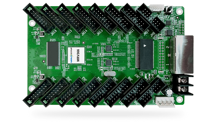
What is the NovaStar MRV366 receiving card?
The NovaStar MRV366 is an LED receiving card for cabinets that use direct HUB75E module connections. It receives the image data sent to that cabinet and distributes it through sixteen integrated module outputs. That gives a large cabinet a compact wiring layout, but it also makes the module ribbons and saved cabinet map part of the replacement decision.
This card is especially relevant for cabinets that require up to 1/64 scan. Its headline capacity is not one fixed number: the official limit is 512 × 256 at 8-bit, then 256 × 256 at 10-bit or 12-bit. If a design moves to the higher-bit-depth path without changing the card plan, it may need a second receiving card even though the cabinet dimensions have not changed.
MRV366 key features
- 1/64-scan support: a module and driver-IC compatibility condition for dense scan layouts. It should agree with the existing cabinet configuration, not be treated as a general picture-quality upgrade.
- Sixteen integrated HUB75E outputs: module ribbons can connect directly to the card. Before replacing one, compare the ribbon positions and module count instead of relying on the name alone.
- Two documented load levels: 512 × 256 at 8-bit and 256 × 256 at 10/12-bit. This is the card-count question that matters when an LED wall needs a higher-bit-depth signal path.
- Configuration and firmware readback: lets a healthy cabinet supply the information needed to restore its own scan, wiring and pixel map to a spare card.
- Mapping, health checks and stored image: make service work more deliberate: identify a cabinet, check the power/link path and keep a planned appearance during a selected signal interruption.
NovaStar MRV366 specifications
These V1.2.0 facts identify the card and set its first cabinet-fit boundaries. The completed module layout and its original configuration are still required before an order is confirmed.
| Maximum card load | 512 × 256 at 8-bit; 256 × 256 at 10-bit / 12-bit |
|---|---|
| Module outputs | 16 integrated standard HUB75 connectors |
| Parallel RGB data | Up to 32 groups |
| Supported scan | Up to 1/64 scan |
| Input / rated power | DC 3.3–5.0 V; 0.5 A; 2.5 W |
| Dimensions | 145.6 × 91.5 × 17.2 mm |
MRV366 capacity at 8-bit, 10-bit and 12-bit
The sixteen module outputs do not each receive a separate 512 × 256 allowance. They share the load of one MRV366. Start by adding the pixel dimensions of every module served by that card, then use the bit depth of the planned signal path before deciding that one card is enough.
| Signal path | Maximum load per MRV366 | Planning result |
|---|---|---|
| 8-bit | 512 × 256 | Use this only when the finished system is truly using the 8-bit condition. |
| 10-bit | 256 × 256 | Recalculate card count; a 512-pixel-wide cabinet may need its load divided. |
| 12-bit | 256 × 256 | Treat it as the same documented loading boundary as 10-bit. |
These are card-wide maximums, not a promise for every possible module design. Scan, driver IC, data-group demand and folded ribbon routing still belong in the final cabinet check. Leaving a margin is safer than making a replacement plan depend on the absolute ceiling.
MRV366 1/64-scan and 16-HUB75E cabinet fit
“Up to 1/64 scan” tells you what kind of module-driving arrangement the card can support. It does not convert a different scan cabinet into a match. For a replacement, read the scan and driver details from a known-good cabinet configuration whenever possible, then compare those details with the new card’s limits.
The MRV366 also puts sixteen standard HUB75 outputs on the board itself. That is useful when a cabinet is built around direct ribbon connections, but the output count alone does not prove compatibility. Photograph the old card before removal, including the full ribbon order. A single shifted connector or a generic file from another wall can create a mirrored, repeated or incomplete image while every component is powered correctly.
Do not assume that a newer receiving card is an automatic upgrade for MRV366. A different board can introduce a new hub, module, configuration or power requirement. For an existing cabinet, the exact model and the original cabinet data are usually the shortest route back to a working screen.
MRV366 status checks and image continuity
Before ordering a card for a dark section of wall, check the easy path first: cabinet power, the incoming and outgoing Ethernet lines, and the module ribbons. With compatible system hardware, the MRV366 can report voltage, temperature and Ethernet bit errors in NovaLCT. Those checks help determine whether the issue is a power, cable or card problem instead of turning every fault into a receiving-card purchase.
Mapping can show the receiving-card number and Ethernet-port information at the cabinet, which is useful when a wall contains many identical tiles. The card can also use a selected stored image for startup or a configured loss-of-signal condition. That can prevent an isolated black cabinet during a planned interruption, but it should never hide a communication or source problem that needs repair.
Where the system supports the relevant functions, calibration, quick seam correction and RGB Gamma controls are tools for correcting visible brightness, color or seam differences. They do not replace the correct configuration data or make mismatched LED modules identical.
MRV366 replacement setup with NovaLCT
Save the working cabinet before replacing it. In NovaLCT, read and keep the receiving-card configuration and firmware information from a known-good MRV366 when it is still reachable. Keep that file with a board-label photo, cabinet location and module-ribbon photo.
The cabinet configuration records that cabinet’s scan, wiring and pixel map. Firmware is a separate program that must match the receiving-card hardware and module electronics. A firmware update cannot recreate a missing cabinet file, and a cabinet file from a wall that only looks similar can produce a wrong image.
Fit the replacement, restore the verified configuration, then test one cabinet before sending any changes across the screen. Use an exact firmware package only when it is verified for the installed hardware and solves a real need. A newer version is not a good reason by itself to disturb a stable display.
MRV366 datasheet, firmware and NovaLCT
The datasheet confirms the 1/64-scan, load and connector limits. NovaLCT protects the cabinet-specific setup before a replacement. Keep a known-good firmware/configuration pair rather than downloading a file because its version number is higher.
NovaStar MRV366 FAQ
What does the MRV366 receiving card do?
It receives mapped screen data in a compatible LED cabinet and distributes it to the cabinet modules through sixteen integrated HUB75 outputs.
What is the MRV366 maximum load at 8-bit?
The official maximum is 512 × 256 pixels for one complete MRV366 at 8-bit. It is shared by all outputs on the card.
Does MRV366 have the same load at 10-bit or 12-bit?
No. The documented maximum is 256 × 256 pixels at 10-bit and 12-bit, so card count may need to change.
Does 1/64 scan make MRV366 compatible with every LED module?
No. It is a supported scan range, not a universal module setting. Match the existing module, driver IC and cabinet configuration.
Why does a new MRV366 show repeated or scrambled content?
The cabinet configuration may be wrong. Restore the configuration from the same cabinet design before assuming the replacement card has failed.
What should I save before an MRV366 card swap?
Save the configuration and firmware information from a working cabinet, plus photos of the board label and all module-ribbon positions.
Can a newer receiver automatically replace MRV366?
No. Verify the hub/ribbon layout, module and driver requirements, power, controller environment and cabinet configuration first.
Should I update MRV366 firmware during a repair?
Not automatically. Restore the known-good cabinet configuration first, then use firmware only when an exact verified package is needed for the installed hardware.
Reviews
There are no reviews yet.