
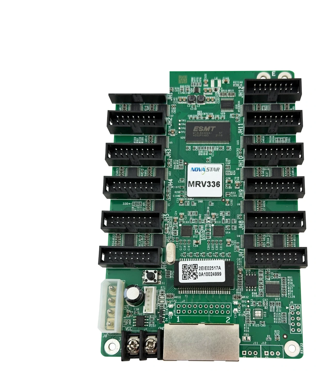
What is the NovaStar MRV336 receiving card?
The NovaStar MRV336 is a receiving card fitted inside an LED cabinet with compatible 1/32-scan modules. It receives the screen data from the controller or a preceding cabinet, then distributes that data directly to the cabinet modules through twelve built-in HUB75E connectors. The integrated connectors remove the need for a separate hub board in the cabinet design.
For most owners, the question is not whether twelve connectors sound useful. It is whether the replacement will restore a screen that already worked. Match the module scan, the ribbon layout and the saved configuration before ordering. A similar card may light the cabinet while still showing repeated, shrunken or scrambled content if it has the wrong cabinet file.
MRV336 key features
- 1/32-scan support: this is a compatibility condition for the module and cabinet, not a general image-quality label. It needs to agree with the working panel configuration.
- Twelve HUB75E outputs: module ribbons connect directly to the card, which keeps the cabinet data path compact and visible during service.
- 24 groups of parallel RGB data: this sets the module-data boundary alongside the total pixel load. Check both values before treating a 12-output layout as a match.
- Configuration readback: a known-good cabinet can provide the information needed to return a spare card to the same scan and module order.
- Stored image and status monitoring: voltage, temperature and Ethernet-status information helps identify whether a fault is in the power, link or receiving-card path before parts are replaced.
NovaStar MRV336 specifications
These V1.1.2 values identify the receiving card and define the first cabinet-fit boundary. The finished module configuration still decides whether the card is the right spare.
| Maximum card load | 256 × 226 pixels |
|---|---|
| Module outputs | 12 standard HUB75E connectors |
| Parallel RGB data | Up to 24 groups |
| Supported scan | Up to 1/32 scan |
| Input / rated power | DC 3.3–5.5 V; 0.5 A; 2.5 W |
| Dimensions | 145.6 × 95.3 × 18.4 mm |
| Operating environment | −20°C to +70°C; 10% to 90% RH, non-condensing |
MRV336 1/32-scan cabinet compatibility
Scan rate describes how the module rows are driven. The MRV336 supports up to 1/32 scan, so it belongs in a cabinet whose modules, driver ICs and existing configuration are built for that range. It does not make a different scan type become compatible just because the card has the same connector style.
Before a replacement, read the existing configuration from a known-good cabinet whenever possible. If the old card is no longer readable, use the cabinet maker’s original file rather than a configuration from a wall that merely looks similar. That one precaution is often the difference between a quick repair and a screen that repeats part of its picture across several modules.
MRV336 capacity across 12 HUB75E outputs
The 256 × 226 maximum belongs to one complete receiving card. It is not a separate allowance for every HUB75E connector. The modules connected to all twelve outputs share that same image-data budget, so a cabinet can use many connectors without being a high-pixel cabinet.
Start with the actual module count and module pixel dimensions, then compare the total against the card limit. Next, confirm the required scan and the 24-group RGB boundary. This order is more reliable than choosing a card from connector count alone, particularly when a cabinet uses non-standard ribbon routing or multiple small modules.
MRV336 replacement: save the right cabinet configuration first
Before unplugging a card that still communicates, use NovaLCT to read and save the working receiving-card settings and cabinet configuration. Save a board photo, the cabinet location and the module-ribbon order with those files. They give the installer a way to restore the original screen rather than rebuild it by trial and error.
A configuration from another MRV336 wall is not automatically safe. The file carries the relationship between the module, scan, wiring and pixel map. When that relationship is wrong, a replacement can show a repeated block, a compressed corner or a picture in the wrong module order even when the card itself is healthy.
MRV336 status checks before replacing a card
When part of a wall is dark, check the simple path first: cabinet power, Ethernet link, module ribbons and whether the cabinets before and after it are working. The MRV336 supports supply-voltage, temperature and Ethernet-communication monitoring, so these are useful clues rather than decorative specifications.
After a spare is installed, test one cabinet before sending a new configuration to every cabinet on the screen. If the image is distorted but the card is powered and communicating, stop and restore the saved file from a known-good tile. Replacing more hardware or updating firmware first can make a recoverable configuration issue harder to trace.
MRV336 or a newer receiving card?
The MRV336 remains a sensible like-for-like choice for an existing compatible 1/32-scan cabinet with twelve direct HUB75E module connections. That approach preserves the established module wiring and gives the saved configuration a clear target.
For a new cabinet or a system moving to newer controller software, do not assume a newer card is a drop-in upgrade. Confirm the module interface, scan, driver IC, cabinet power and controller ecosystem together. If you are unsure which rule applies, send the card label, both sides of the board, module-ribbon photo and saved configuration through our compatibility support form before ordering.
MRV336 manual, datasheet, firmware and NovaLCT
The datasheet confirms the card’s electrical and cabinet-fit limits; NovaLCT is the practical tool for protecting a known-good configuration. Firmware must match the exact card and module electronics, so keep a stable version unless an exact, verified package addresses a real issue.
NovaStar MRV336 FAQ
What does the MRV336 receiving card do?
It receives mapped screen data inside a compatible LED cabinet and sends it directly to the cabinet modules through twelve HUB75E connectors.
Does the MRV336 support 1/32 scan?
Yes. Confirm that the installed module and cabinet configuration need that scan range before using it as a replacement.
Is 256 × 226 available on every MRV336 connector?
No. That is the maximum load for one complete card. All twelve outputs share it.
Why is my image repeated after replacing an MRV336?
The spare may need the configuration from the same cabinet design. Read it from a known-good cabinet or use the original cabinet file before changing other hardware.
What should I save before an MRV336 replacement?
Save receiving-card settings, the cabinet configuration, a board-label photo and the module-ribbon order.
Can a newer receiving card replace MRV336 automatically?
No. Match the module interface, scan, driver IC, power, wiring and controller ecosystem first.
Should I update MRV336 firmware before a repair?
Only with a verified package for the exact hardware. Restore the known-good configuration first when the existing system was stable.
Can you check my MRV336 cabinet before I order?
Yes. Send clear photos of the board and module ribbons, cabinet details and the saved configuration if available.
Reviews
There are no reviews yet.