
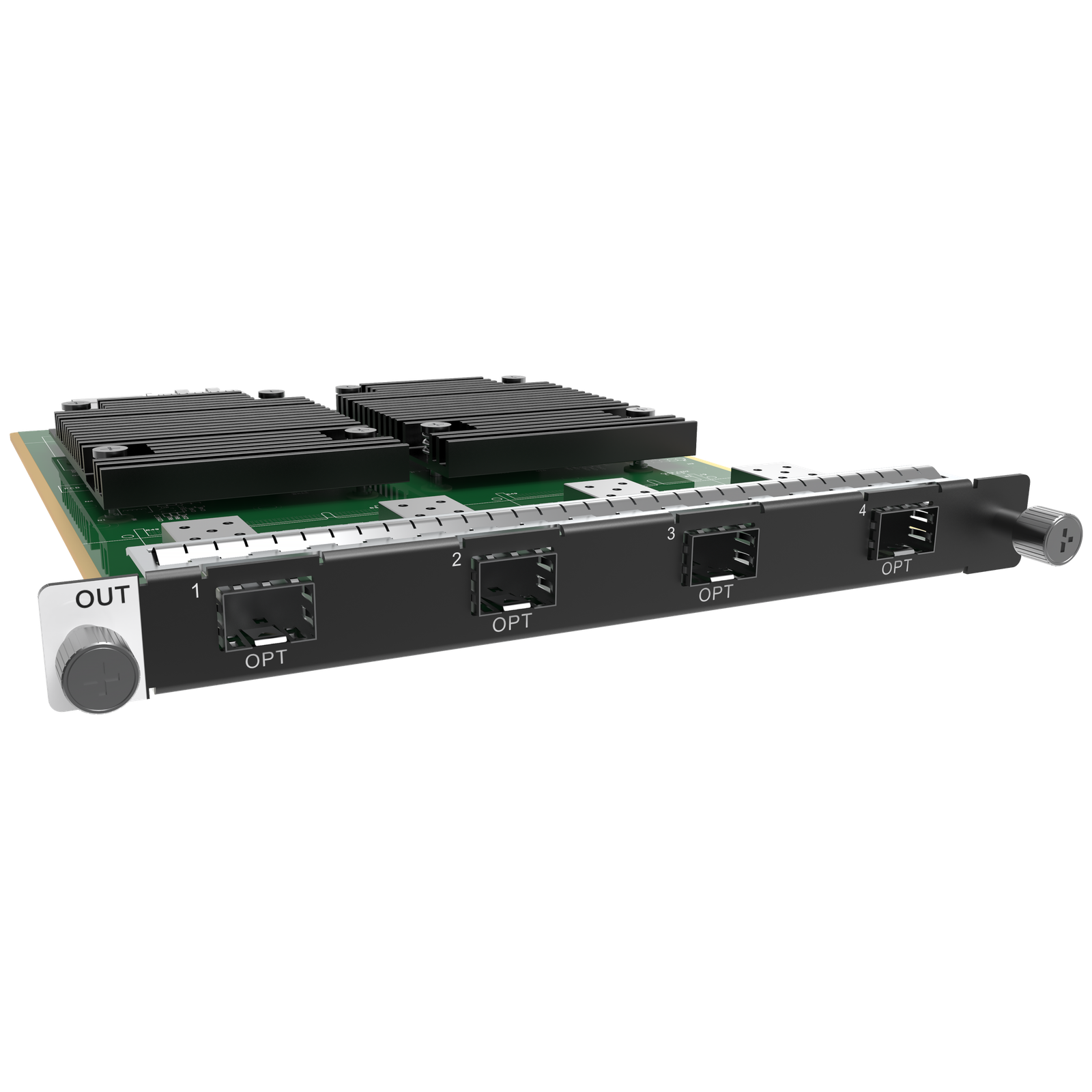
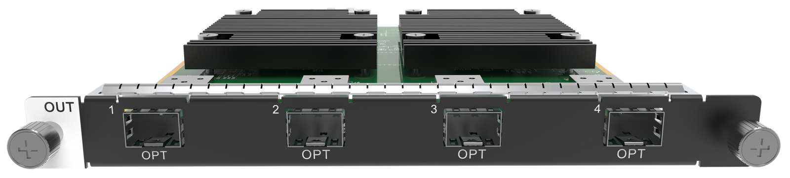
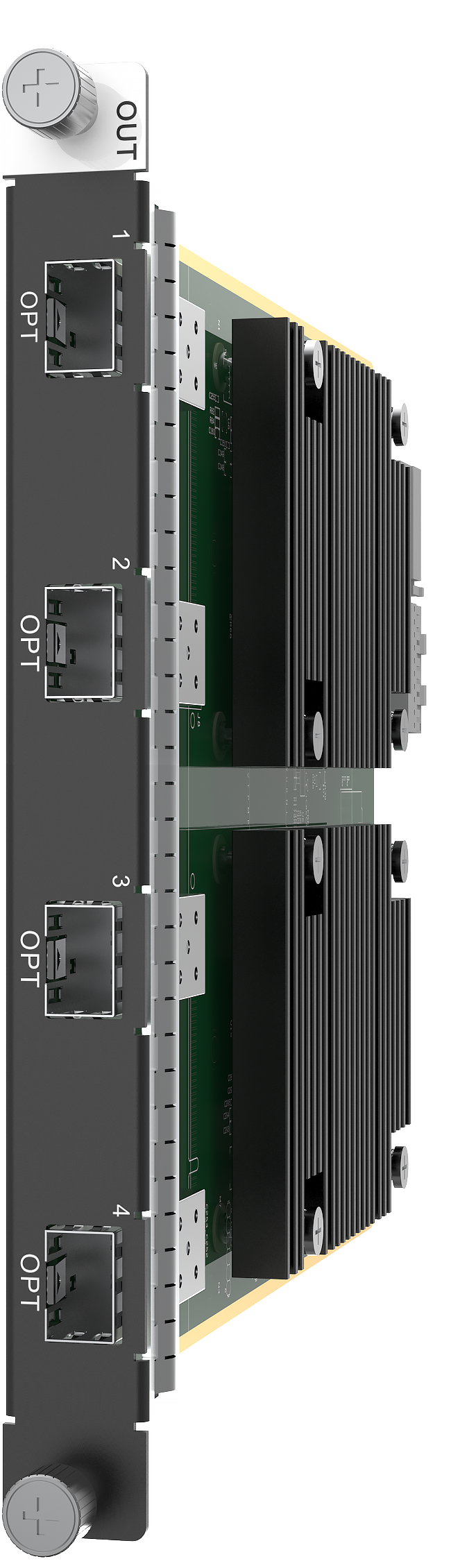
What is NovaStar H_4x Fiber output card?
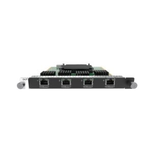
The NovaStar™ H Series 4x Fiber Output Card is an LED sending card for a compatible H Series chassis. After the chassis has arranged the video sources into the required LED layout, this card carries that completed LED data over planned 10G fiber routes to cabinet-side fiber equipment and, ultimately, the LED cabinets.
It is an output card, not the H Series video wall splicer and not a fiber source-input card. The decision is not simply “four fiber ports.” Choose the working mode first: four independent LED routes, two main routes with matching copies, or two main routes with matching backup paths. The selected mode decides what each OPT port is allowed to do.
The standard card includes four installed 10G SFP+ LR single-mode modules. If the project’s optical plant is multi-mode SR instead, NovaStar documents a separately named H_4xfiber Sending Card-M. If the fiber is meant to bring remote video into the chassis, this is the wrong direction; see the H_4x Fiber Input Card.
Request H_4x Fiber output card bulk pricing →
For confirmed multi-card H Series or project quantities.
NovaStar H_4x Fiber output card key features: what makes it different?
- Move a large LED layout onto optical routes: one card can load up to 20.8 million pixels. This is the maximum for the card as a whole, not a 20.8-million-pixel allowance for every individual OPT port.
- Choose four independent routes when the screen plan needs them: Independent mode makes OPT 1–4 four primary LED-data outputs. Each one has the loading capacity of eight Ethernet ports, giving a large system four separately planned optical paths.
- Build deliberate protection into a two-route design: Copy mode mirrors the two main routes, while Backup mode reserves a second route for each main path. These modes are for matching the actual cable and redundancy plan—not for creating four unrelated primary outputs.
- Start with the standard long-run optical modules installed: this card includes four 10G SFP+ LR single-mode modules. It also supports SR multi-mode modules, but the route type, connector count and cabinet-side equipment must match before the system is ordered.
- Plan an irregular cabinet route only when the receiving-card design supports it: NovaStar documents free topology for specific receiving cards. It can help a non-rectangular LED layout, but it is not a feature to assume for every cabinet system.
- Keep one limitation visible during show planning: NovaStar specifies 8-bit and 10-bit output and up to 144 Hz, but the LED screen loaded by this standard card does not support fade transitions. Select the Enhanced fiber card only when that different output behavior is a confirmed requirement.
NovaStar H_4x Fiber output card specifications
These are output-card facts. The H Series chassis creates the layout; the completed cabinet path also depends on the planned optical route, converter, receiving cards and cabinet map.
NovaStar H_4x Fiber output card modes: independent, copy or backup?
This is the decision that changes the usable port map. Make it before the fiber is installed. A Copy route duplicates the main picture intentionally; a Backup route waits to protect it. Neither is a fourth independent LED output.
If the project needs a different fiber-card behavior—such as the Enhanced card’s paired backup/copy ports, higher 26-million-pixel maximum or fade-transition support—compare the H_4xFiber Sending Card (Enhanced) before committing to the port map.
NovaStar H_4x Fiber output card vs H_4xFiber sending card (Enhanced)
Choose by the route pattern first. The standard card is the better fit when all four OPT ports need to be independent primary routes. The Enhanced card is for a different design: four primary routes, each with a paired Copy or Backup route, plus a larger card-level load and fade-transition support.
The cards cannot load the same LED screen together. Choose one card type for that screen and set the port mode around the real cabinet route before ordering.
How NovaStar H_4x Fiber output card sends an LED layout over fiber
These are consecutive steps. The output card starts only after the H Series chassis has completed the screen layout.
- Build the video layout in the H Series chassis. Cameras, playback or other input-card sources are arranged into the final LED canvas. For the system role, see the NovaStar H15 video wall splicer.
- Choose the output-card mode from the real path plan. Set Independent for four primary routes, Copy for intentionally mirrored routes, or Backup for two protected main routes.
- Carry the finished LED data over the correct optical links. Match the standard LR modules or appropriate SR alternative to the actual fiber plant. NovaStar recommends a CVT Series fiber converter at the OPT port.
- Configure the cabinet side and validate the complete route. The converter, receiving cards, cabinet files and physical cabinet map must agree with the selected port plan. Use NovaLCT for the receiving-card and screen-mapping work.
NovaStar H_4x Fiber output card applications
These situations are about carrying a finished H Series LED layout from the central rack toward cabinet-side equipment. They are not remote-source input uses.
Long LED runs from a central rack
Use a properly matched optical route when the video wall is located well beyond a practical local copper run and the cabinet-side conversion path is already defined.
Large fixed LED canvas
Use the card when one H Series output-card design needs to carry a high pixel load and the total screen stays inside the card’s 20.8-million-pixel maximum.
Mirrored LED paths
Copy mode fits a design where two main optical outputs must be deliberately repeated at a second planned path, rather than treated as four separate output areas.
Protected show or operations route
Backup mode suits installations that have physically planned redundant fiber and cabinet-side paths for each of two main optical routes.
NovaStar H_4x Fiber output card compatibility and setup
Compatibility starts at the H Series chassis: confirm a suitable output-card position, then confirm the screen’s total load and choose the right mode before pulling fiber. The standard card’s included LR modules are intended for a matching single-mode route; the multi-mode decision must match the actual hardware, not a preference on site. Browse the H Series collection only after the chassis, output slot and cabinet route are defined.
NovaStar specifies NovaLCT V5.4.8 or later to configure a screen loaded by this card. Use it to apply the output bit depth and receiving-card/cabinet map after the route is installed. A CVT fiber converter and compatible NovaStar receiving cards are cabinet-side decisions; this card does not remove that planning work.
NovaStar H_4x Fiber output card manual, datasheet and H Series firmware
NovaStar documents this modular sending card within its H20 specifications rather than as a separate public card-only PDF. The first resource is the current card-containing reference; the other files are clearly labelled H Series family resources.
NovaStar H_4x Fiber Output Card specifications (PDF)
Current official H20 document that includes the standard card’s modes, load, optics, dimensions and power.
NovaStar H Series user manual (PDF, V1.15.0)
Official H Series output-card setup and operating guidance.
NovaStar H Series firmware (ZIP, V2.2.0.0)
Verified H Series family package; it is not presented as card-only firmware.
NovaStar H Series release notes (TXT, V2.2.0.0)
Official changes and update notes for the H Series family package.
NovaStar H_4x Fiber output card FAQs
Is the NovaStar H_4x Fiber Output Card a video wall splicer?
No. It is an H Series fiber LED sending/output card. The compatible H Series chassis creates the video layout; this card sends the completed LED data along the planned optical routes.
Is this card for bringing a remote fiber video source into the chassis?
No. This is the output direction, from the H Series chassis toward cabinet-side fiber equipment. Use the H_4x Fiber Input Card when the optical video source must enter the chassis.
Does the standard H_4x Fiber Output Card include optical modules?
Yes. NovaStar documents four installed 10G SFP+ LR single-mode modules with the standard H_4xfiber Sending Card. The project’s physical fiber route must match that module type.
What does the 20.8-million-pixel maximum mean?
It is the maximum load for one card, not the capacity of each OPT port and not a number to multiply by four. The complete cabinet map and selected mode still need to stay within the documented card and chassis plan.
Can all four OPT ports work as independent LED routes?
Yes, in Independent mode. Once Copy or Backup is selected, OPT 3 and OPT 4 are assigned to copy or protect the two main outputs rather than act as unrelated primary routes.
What is the difference between Copy and Backup mode?
Copy mode repeats OPT 1 on OPT 3 and OPT 2 on OPT 4. Backup mode sets OPT 3 as the backup of OPT 1 and OPT 4 as the backup of OPT 2. Choose the one that matches the actual installed route.
Can the screen use fade transitions with this card?
No. NovaStar states that the screen loaded by this standard H_4xfiber Sending Card does not support fade transitions. That is a separate comparison point for the Enhanced model.
Do I need a converter and receiving cards?
The output card is only one stage of the cabinet-side path. NovaStar recommends a CVT Series fiber converter at the OPT port, and the final LED system still needs compatible receiving cards and a verified cabinet map.
Is the firmware download a card-only update?
No. The listed file is a verified H Series chassis/family firmware package. Read its release notes and the selected chassis documentation before any update.
Reviews
There are no reviews yet.